1

A 3-wire loadcell have two strain gages with a no load resistance of R.

When a load is applied, the resistance of one strain gauge will change to R+dR and the other will change to R-dR (because one stretches and the other one compress).

How can I calculate dR?

How can I calculate the dR for this sensor especification for example? Where I have a capacity of 50kg and an Output Sensitivity of 1mv/v ?

Thanks

koike
  • 283
  • 1
  • 6
  • 14
  • looks underspecified to me. – Scott Seidman Apr 09 '14 at 22:20
  • @ScottSeidman: And for [this other loadcell?](http://www.manyyear.com/Weighing/Weighing_scale_sensor/kitchen%20scale%20weight%20sensor%20MLC913E.html) – koike Apr 10 '14 at 11:51
  • That tells you the output, not the output sensitivity, so Sphero's approach seems right. It might be right for the original case, too, but the spec sheet is misusing the term "sensitivity" – Scott Seidman Apr 10 '14 at 14:01

2 Answers2

2

That appears to be the specification for two half-bridges used in a full bridge configuration. The input Z is 1k and the output Z is 1K, so that would imply that each arm is 1K.

enter image description here

It says 40-50kg for full scale, but it's not clear whether that's the total weight or not.

Let's assume it's 45 kg total (22.5 kg for each sensor).

Assuming it is the total, the nominal output sensitivity is 1mV/V +/-10%. If we assume the half-bridge has an output of half that (500uV/V) then each resistor must change 0.1% at full capacity.

Edit: We know that the output voltage of a voltage divider consisting of approximately equal resistors is changing by 0.05% of the total excitation (500uV/V), therefore if the two resistors change the same amount in opposite directions, the total resistance will remain the same and each resistor must change by 0.1% for the output voltage to change by 0.05% of the excitation voltage.

schematic

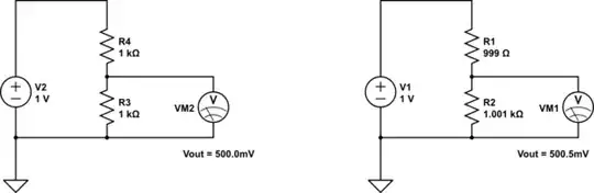
simulate this circuit – Schematic created using CircuitLab

So \$\Delta R\$ is 1\$\Omega\$/22.5Kg or 44.4m\$\Omega\$ per kg +/-10%.

Spehro Pefhany
  • 376,485
  • 21
  • 320
  • 842
  • Huh?? Where does 0.1% come from?? – Scott Seidman Apr 10 '14 at 03:22
  • @ScottSeidman K, there you go. – Spehro Pefhany Apr 10 '14 at 03:31
  • @SpehroPefhany Hi, thanks for the response. But I didn't understand how do you know that this specification is for the full bridge arrangement? Is this [other specification](http://www.manyyear.com/Weighing/Weighing_scale_sensor/kitchen%20scale%20weight%20sensor%20MLC913E.html) for a full brigde too? – koike Apr 10 '14 at 11:48
  • @koike It sure is, as you can tell from the schematic. That load cell includes a full bridge. – Spehro Pefhany Apr 10 '14 at 12:06
  • I think the issue is whether the 1mV/V means 1mV/V/50kg. I haven't seen load cells parametrized that way. It might well be 1mv/V/1kg, and the output change from zero to full scale might be 50mV. – Scott Seidman Apr 10 '14 at 13:44
  • @ScottSeidman Well, you can look at this: http://www.aandd.jp/products/weighing/loadcell/introduction/pdf/6-1.pdf See the example calculation. If the sensitivity is 1mV/V-kg it should say so. The reason why full scale makes sense is that the maker can easily change the mechanical design (such as beam cross section) to have different forces for full scale, but the mV/V at full scale will be the same. – Spehro Pefhany Apr 10 '14 at 13:49
  • @SpehroPefhany, agreed, and if the sensitivity is 1mV/V-50kg, it should say that, too! – Scott Seidman Apr 10 '14 at 13:51
  • The term I'm having trouble with is Output Sensitivity, which is not in your last link, nor, omega's load cell spec. http://www.omega.com/Pressure/pdf/LC101.pdf Output certainly means over full scale. Sensitivity USUALLY means unit output per unit input. FWIW, I think you're correct, and the term is misused here, but it's not 100% for me. – Scott Seidman Apr 10 '14 at 13:59
  • 1
    @ScottSeidman It's the standard way to specify a load cell from what I've seen. Another tack..is 50mV/V @ FS plausible for a load cell? The example one I linked to is 1mV/V @ FS. My interpretation of the Chinese one is 2mV/V @ FS. 50mV/V would have to be made with different technology. – Spehro Pefhany Apr 10 '14 at 14:07
  • If the "standard way" is used in your last link, and in Omega's spec sheet, those both say "output" and not "output sensitivity", and those are both clear to me. – Scott Seidman Apr 10 '14 at 14:09
  • 1
    P.S. From long years of dealing with offshore suppliers, I tend to take the exact English words they use a lot less seriously than the numbers. – Spehro Pefhany Apr 10 '14 at 14:10
  • @SpehroPefhany, it is weird for me that the rated output (mv/v) considers the the whole bridge as I can arrange the 3-wire loadcells as I want, but ok, I can live with this :) . I asked this question because I am hacking a kitchen scale with four 3-wires loadcell and I check they are connected like [this bridge](http://electronics.stackexchange.com/questions/92946/combination-of-four-half-bridge-load-cells) (I checked with the multimeter that they are "circularly" connected). Thus to calculate the new output rate I should know the dR, am I right? – koike Apr 10 '14 at 20:02
  • @koike Won't you just put a calibrated test mass on the bridge-connected sensors and measure the output voltage change? – Spehro Pefhany Apr 10 '14 at 20:25
  • @SpehroPefhany, yes, but I feel that my prototypes are not that good and I don't know if the values that I am reading are close to the theoretical one (because I don't know the theoretical one) or because I am doing a bad measurement. – koike Apr 10 '14 at 20:42
  • 1
    @koike, your measurement is all that is important. Take calibrated test masses, measure the change between say, 10 and 30 kgs, extrapolate backward to find your y-intercept and repeat for every load cell you have. I use strain gauges quite a bit to measure suspension loading on race cars, and if there's one I've learnt, its that every strain gauge behaves differently and you should treat them as such. Measure multiple times, average, and record the y-intercept and the slope for each individual strain gauge. There are too many variables to make assumptions of when it comes to strain gauges – c10yas May 03 '19 at 17:47
1

The stiffness of the beam needs to be known, and from that, the quantity known as micro-strain calculated for the loadcell at it's mounting position. Then you need to know the gauge's "gauge factor" then it's calculatable.

From the spec shown in the question it's impossible to calculate. More info needed.

Andy aka
  • 434,556
  • 28
  • 351
  • 777
  • Hi! Thanks for the answer. Do you mean that the explanation given by @SpehroPefhany is not valid? – koike Apr 10 '14 at 11:50
  • 1
    I was first to answer so my answer does not make any criticism of answers that may follow. For the first part of your question I have given the only answer I felt was correct. In the second part of your question you give an example that I believe doesn't have enough info to make the assumptions that Spehro has made but he could easily be correct in his judgement. – Andy aka Apr 10 '14 at 12:10
  • @Andyaka Or I could be full of it. ;-) This is data supplied with a product sold by Sparkfun, so it's *intended* to be sufficient. – Spehro Pefhany Apr 10 '14 at 13:54
  • @Andyaka Sorry, I didn't mean that you were criticising him, I was just trying to understand the compatibility of both answers. You are all being so helpful. I would give up votes in most of the comments and answers but I don't have enough reputation yet =/. Thanks. – koike Apr 10 '14 at 20:06