You should be able to run the relay from either a BJT or a MOSFET. For this application the important thing to remember are; the voltage / current requirement of the relay coil, the operating voltage of your circuit and the voltage of the control signal.
When choosing components with so many parameters i usually use a suppliers parametric search feature, and input the characteristics i want from the component.
See:
BJT: http://uk.farnell.com/transistors-bipolar-bjt-single
MOSFET: http://uk.farnell.com/mosfets
For BJTs it's usually; Collector-Emitter voltage (Vce), Collector current (Ic) and Base-Emitter Current (Ibe). So in your case; Vce > 5 | VIc > 200 mA
And for MOSFETs it's usually; Drain Current (Id), Drain-Source Voltage (Vds), and the threshold Gate-Source Voltage (Vgs). So in your case; Id > 200 mA | Vds > 5 V | Vgs 5V (you want to operate in saturation)
Don't worry if for the current and voltage ratings the component you select has a much higher value, the important values are the switch on thresholds.
You can just connect the output of your uP to the gate of the FET or BJT but this is a bad idea (It usually ends in the magic smoke escaping from your expensive IC). Ideally you should have a current limiting resistor and a pull-down. You can (and probably should) calculate values for these resistors, though in practice I've found that 1k and 10k work for 99% of situations.
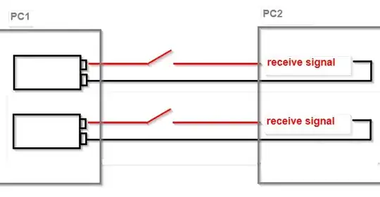
Here are some examples of circuits i use / have used to control relays in the past. All of these are low side switching examples, and a +ve signal from the uP will switch on the relay.
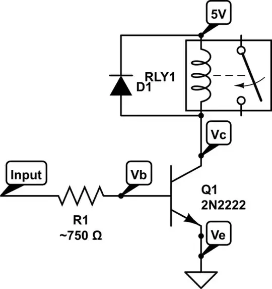
Using a NPN BJT
simulate this circuit – Schematic created using CircuitLab
Using a N-MOSFET
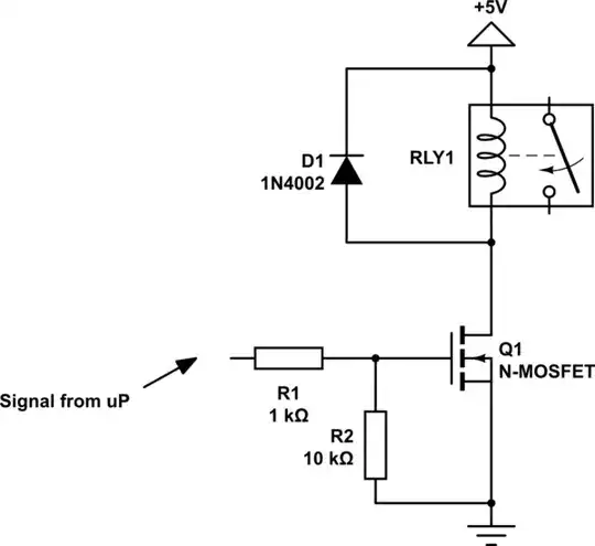
simulate this circuit
Hope this helps,
-- EP