1

I am using Atmega328P to read temperature from LM35 and display it on the LCD (along with few several things it does).

I want to understand the capacitor and connections for the AVR itself and AVcc.

I read stuff online, about decoupling, bursts, under-power and such, but I did not understand what I should connect to do it right.

Some said I need to connect 10uF electrolytic cap to Vcc and ground, and to AVcc and ground.

Others said I need to connect ceramic 0.1uF to Vcc and GND and AVcc and GND. Some said both.

I am confused, really confused :)

Also, I am starting to think I need to recheck my LM1117 3.3V regulator caps, I am using 2 10uF caps (Input V and GND, and 3.3V and GND).

Can you help please?

JYelton
  • 32,302
  • 33
  • 134
  • 249
gabi
  • 343
  • 2
  • 5
  • 17
  • I'm also confused. Do you need help with understanding how to properly decouple and filter your AVcc and Vcc? Are you also having problem reading your LM35? – Dejvid_no1 Apr 08 '14 at 19:51
  • It looks like the LM35 reading a bit low than the actual temperature, But I also want to understand the capacitors needs and what is needed to get better "guerd" of the AVR and ADC stable reading.. Thanks. – gabi Apr 08 '14 at 20:00
  • follow manufacturer guidelines.....there are lots of app notes regarding decoupling capacitor selection and placement in web... – user19579 Apr 09 '14 at 05:22

3 Answers3

7

I will first talk about decoupling capacitors, and then specifically the options the Atmel 328P has for it's AVCC and AREF pins.

Decoupling capacitors are used to provide short bursts of energy during digital switching circuits (they go from zero to full voltage in a very short amount of time, they need energy and available current source nearby to do this) and as a general value everybody just puts 100nF (0.1uF) capacitors at the power pins of every single IC used in their boards. This is a safe and good strategy. It is not, however, strictly needed unless your system is large and complex. If you have a regulator (with it's own capacitors) very close to your Atmega you will be fine with out them.

Your regulator is fine with a 10uF capacitor on the input and output, you do not need to change those. In the future though, you should ALWAYS consult your regulator's datasheet. Some regulators cannot use high "ESR" capacitors as they can cause unstable operation, and likewise some regulators cannot handle ultra-low ESR capacitors like Ceramic capacitors because they will "ring" and ripple uncontrollably (overshoot constantly) among other hilarious power control system challenges.

AVCC is the analog voltage supply used internally by the ADC and is most commonly internally connected to the AREF pin, used directly as the reference for ADC readings. You can either filter and decouple AREF, or VCC, but the one that matters most depends on what you actually want for your ADC. The Atmel328P has internal Vref (2.56V or other ones) you can select, for exampl. You can also provide your own reference voltage at the AREF pin, and other than power supply ripple your AVCC becomes less important in terms of filtering. You might have bought a precision 3V reference IC, and followed it's datasheet guidelines for suggested circuit, and then put the Vout into the AREF pin of the AVR. In this case, AVCC can be left with either:

  • direct connection to VCC
  • or a simple decouple 0.1uF cap to help with local noise filtering
  • with an inductor or ferrite bead in series from VCC into the AVCC for AC current ripples, and if you put a capacitor to ground here as well (AFTER the inductor), it becomes a current AND voltage ripple filter - nice and clean!

AREF could be left unconnected, and merely filter VCC. Often if the AREF pin is un-used and AVCC And AREF are internally connected, you can put a 0.1uF capacitor on the AREF pin, which will have the same effect as putting the capacitor on AVCC due to the internal connection. Maybe this can assist with circuit layout?

If you have a slow, steady state error on your temperature sensor, I bet you it's not related at all to ADC or power supply filtering - I bet that the error is within tolerances given by the datasheet (usually +-15% which is quite a lot!). You almost always need to (usually only once) 'calibrate' your ADC readings by getting a known (working) thermometer at ambient temperature nearby, and adjust the offset of readings to make it line up with expectations. The sensor's rate of change (mV/Degrees celcius) should still be fine, it's just the 'steady state error' inherent to low tolerance manufacturing.
KyranF
  • 6,248
  • 16
  • 25
  • Sorry to comment this old post, but i have one question: If we use the inductor for AVCC does we also need power analog devices from filtered AVCC or doesn't matter if we use the 5V for analog devices? I heard somewhere if not use AVCC we can introduce noise into analog circuit but we also missing a AGND on MCU... – Tiago Conceição Jul 17 '19 at 22:30
  • 1
    hello @TiagoConceição, it's okay to ask questions in the comment. If you use the inductor (or ferrite bead) and capacitors and filter the 5V supply (VCC) to create a cleaner supply (AVCC), you should power your low-power analogue devices from that if you can. Power supply noise is a big problem for sensitive analogue devices, and often shows up in the analogue outputs. Having only AVCC for your microcontroller just means the -readings- will be clean, but the data is still coming from a noisy source if you only power it from VCC. Use AVCC if you can! I hope that helps. – KyranF Jul 18 '19 at 08:08
  • So i guess when using potentiometers or resistors to just read the value it's not an advantage using that filtered source? But will be good for example when using with amplifiers? Also another example: MAX6675, doesn't return a analog output to MCU (SPI) but the ic is reading one, it will be usefull to power the MAX6675 from AVCC or it already filter the signal inside the chip? – Tiago Conceição Jul 18 '19 at 19:14
  • 1
    if you need high quality readings, you should also supply any resistor dividers and potentiometers circuits with AVCC instead of VCC. The MAX6675 should be given the filtered AVCC input, because internally it will be using it as a reference and to power its internal ADC.. there is something called "PSRR" or power supply rejection ratio - this is how good a chip is at rejecting/filtering noise out of its supply voltage rail and not having supply noise end up in the output signal. – KyranF Jul 18 '19 at 20:41
  • Thank you, very good information here! About inductor VS bread what would be the best choise? Or doesn't matter for this application? – Tiago Conceição Jul 19 '19 at 18:51
  • 1
    Go for a ferrite bead, they are usually smaller, cheaper, and low-power enough to do the job. They behave a little less 'aggressively' than a real inductor. just resistive at high freq. They don't store as much magnetic field so they are less likely to have the inductive voltage spike which happens when supply is suddenly taken away from them from stored magnetic field. A ferrite bead is a better choice for filtering out power supply noise, whereas an inductor is better for larger scale filtering and power circuits (from my experience) – KyranF Jul 19 '19 at 19:53
  • ok then what ferrite value will correctly replace the 10uH? Since they come as Ohms? My VCC=5V – Tiago Conceição Jul 19 '19 at 20:09
  • 1
    Why would you want 10uH? that seems like a lot for a filter. The ferrite beads act as resistors to signals/power noise which has 'high frequency'. The resistance absorbs the energy and reduces the filtered circuitry from seeing the noise as strongly. Calculate a low pass filter with cut-off band at maybe 10Khz, using the ferrite bead resistance at 10khz from the part datasheet. then specify a capacitor to finish off the low-pass filter. E.g ferrite is 5ohm at 10khz, nearest standard capacitor value is 3.3uF to get a cut-off freq of 9.6Khz. It is even more powerful filter at high freq! – KyranF Jul 20 '19 at 12:23
  • I took the 10uH value from examples i search arround internet, was present in almost every example for atmega328, others in datasheets... I search parts for your example, but datasheets shows R for test frequency at 100MHz, eg. Murata EMIFIL BLM15 http://www.mouser.com/ds/2/281/L0110S0100BLM15BX-225613.pdf How can i calculate resistance at 10KHz using that part? – Tiago Conceição Jul 20 '19 at 19:20
  • just look for parts with very high resistances at 10-100Mhz, and linearly estimate back down to 10khz. So 2.5k Ohm at 100Mhz will be around 250 ohms at 1MHz, or 25 at 100Khz, 2.5 ohm at 10khz, and the DC resistance for those high resistance chips might be ~1.5 ohm already, making the total resistance at 10khz 4 ohms. If you can't get a higher resistance, you can always double the capacitance :) – KyranF Jul 22 '19 at 07:41
  • Humm lets see if i got it: Imagine i pick (BLM15BX102SN1) 1k @100Mhz bead, then 10khz cutt-off would be about 1ohm and C1=16uf? But 1ohm is low, lets put 8ohm there as you suggested, C1 = 2uF and will have R = 8ohm cutoff @ 10Khz. Is that right math? One thing that i didn't understand is how you turn 2500 ohm @ 100MHz into 250ohms at 1MHz, why 25000/100 instead of 2500/100? – Tiago Conceição Jul 23 '19 at 03:04
  • Also by double the capacitance don't resistance go lower? Then should be half the capacitance to increase R? – Tiago Conceição Jul 23 '19 at 03:11
  • Looks like I made a mistake going from 100Mhz to 1Mhz, so you are right there. Anyway if you double the capacitance it doesn't affect the resistance. If you have two capacitors in parallel, it will make their equivalent series resistance lower, but that doesn't matter for the RC low-pass filter, only the series pass-resistor (ferrite bead in this case) matters. Unless your capacitors are very high resistance, for filters you want low "ESR" capacitors (ceramic caps are best for this task) – KyranF Jul 23 '19 at 08:59
  • I think i got it now. Yes the R i was talking was the from ferrite. Thank you for all your explanation & time :) – Tiago Conceição Jul 24 '19 at 00:45
  • if you follow some example application notes on good choice of ferrite bead (see their part numbers used) and capacitors you should be okay – KyranF Jul 24 '19 at 11:14
  • Hard to find with atmel, seems all examples are using the 10uH inductor and datasheet have it as well – Tiago Conceição Jul 25 '19 at 12:13
  • here's one which might be a good read: https://www.analog.com/media/en/technical-documentation/application-notes/AN-1368.pdf – KyranF Jul 25 '19 at 18:45
1

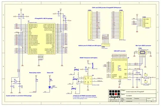
The left side of the image shows how to interface ATmeaga664. However, the principle is the same for the 328 model, I believe:

enter image description here

If you do not have any other power consumption except your microcontroller, you might not need a 10uF cap. But I would suggest to use both 10uF and 100nF in parallel. I had a similar question here. Notice, that analog AVCC is connected to supply through an inductor. Do not know what it is for. Look at the datasheet, I they might have some examples.

Edit: According to LM1117 the datasheet, there should be a 10uF on the input and the output. Then do so.

Nazar
  • 3,142
  • 4
  • 35
  • 62
1

I suggest that you head over to Atmels site and search for their application notes on ADC or power supply considerations. Although application note Atmel AVR32837 is for a totally different CPU it as some explanatory pictures of capacitor values and connections. Application not Atmel AVR042 might be good for you also.

Check your LM35 with a voltmeter and check if it there is a difference with your reading.

Dejvid_no1
  • 3,568
  • 17
  • 24