6

I'm designing a PCB that has a 2.4GHz signal that I'm routing to an SMA jack. I'm trying to figure out the geometry of the necessary microstrip trace. This is the first rf PCB I've worked on.

The problem is that if I feed the values into different online calcuators, I get considerably different values! I don't know which ones to design to.

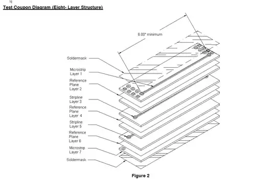
I'm using a 4-layer PCB, 32-mil thick, FR4. The ground plane is directly under the microstrip, with 5.6-mil of prepreg between them. The microstrip thickness is 1.35-mil (1oz copper). I'm assuming a dielectric of 4.2.

The trace is running from a bandpass filter to the antenna jack, and is only 135-long.

Say that I make a 10-mil wide trace. Here are the results:

eeweb.com = 37.1 Ohm.

chemandy.com = 52.2 Ohm using one set of formulas, or 46.85 Ohm using IPC-2121.

If I use formulas from this textbook, I get 42.55 Ohm.

This is a surprising spread. What is the best practice here?

Thanks!

bitsmack
  • 16,747
  • 9
  • 52
  • 108
  • Can you get some advice from the PCB manufacturer? Are you specifying controlled impedance with a test coupon? – Spehro Pefhany Apr 04 '14 at 17:49
  • @SpehroPefhany That's a good idea, I'll call them. They gave me their standard 32-mil stackup, which is what I'm designing to. Do I have to specify controlled impedance, even though it's their standard stackup? Also, I'm sorry, I don't know what you mean by a "test coupon". – bitsmack Apr 04 '14 at 18:03
  • I'll put this in the form of an answer so I can link some photos. – Spehro Pefhany Apr 04 '14 at 18:04

3 Answers3

4

I ran the calculation for you in Cadence SigXplorer (my favorite tool for this and a lot more):

50R parameters

This is a 10.25mil wide trace (sorry units on the image are in metric) to give 50R pretty closely.

Always use a 2D field solver for this (as you noticed, formulas are not enough).

Be aware that the SMA footprint may not be a smooth 50R without some great care as well. For this you can often get help from the connector manufacturer if you send them your stackup (and is deemed a worthy customer :-).

Disclaimer: I provide training in signal integrity often using tools kindly provided by Cadence. Other than that, I am not affiliated. Other tools can do the same thing. The only free one I have tried is called TNT.

Rolf Ostergaard
  • 4,448
  • 18
  • 24
  • Thank you for the analysis. I have the basic Cadence pack, without SigXplorer. If I start doing a lot of these, I guess I should upgrade :) – bitsmack Apr 07 '14 at 06:35
3

My suggestion is to take information from your PCB manufacturer as primary, and the online calculators as a double-check.

If you specify controlled impedance with a tolerance, then you'll normally have to pay something of a premium, depending on the tolerance required. 10% or 5% are common tolerances, though most high-end makers say they can do better (with exponentially increasing cost, I suspect).

You'll want to be able to verify that the manufacturer has done what they say. One method is with a test coupon located in an otherwise unused area of the PCB panel (so it is essentially a second design of PCB included on the same panel with your PCBs).

Here's an 8-layer design from an application note entitled Controlled Impedance Test by Martyn Gaudion:

enter image description here

And the cross-section from the same source:

enter image description here

If the PCB manufacturer does the panelization, they'll probably do this themselves.

Of course, another method is to directly measure the traces you care about, but that might not be easy if the traces are buried and there are not connectors available to attach to them. You can add pads that are not used in production versions, but that will cause reflections.

TonyM
  • 21,742
  • 4
  • 39
  • 62
Spehro Pefhany
  • 376,485
  • 21
  • 320
  • 842
  • Thank you! I have never come across the idea of a test coupon before. – bitsmack Apr 07 '14 at 06:36
  • @Spehro The linke is now broken, sadly. Could you possibly provide an update? – pfabri Nov 23 '20 at 20:15
  • @pfabri the company Merix who provided the data, a fairly large PCB making spin-off of Tektronix in Oregon with China-based production, was acquired and the successor company TTM does not appear to have put the data online, nor does the file appear to exist elsewhere such as in the Wayback. I’ll leave the dead link intact in case the successor firm gets around to putting it online. – Spehro Pefhany Nov 23 '20 at 20:36
2

Best practice is to specify controlled impedance, but that costs money.

For my home projects, I use the Wcalc calculator, since it is open source and tells you where it got its formulas from. Most of the online calculators aren't so transparent on that front.

As a cross-check, and for unconventional geometries, I use MDTLC, which is a 2D field solver. The site shows some comparisons to commercial calculators.

mng
  • 1,330
  • 8
  • 9