Questions, which, with any luck, might turn into an answer.
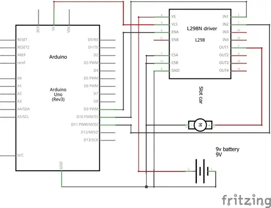
You appear to be using the 298 just as a simple transistor switch, rather than as the full-bridge driver it's intended to be. That's OK, though it would be less confusing if you just used a transistor. (But perhaps you're going to use it in more elaborate fashion later?)
Anyhow... test procedure:
Step 1. Test the motor: Separate from the circuit you showed: Connect the motor to the 9V battery -- does it run? If so, it can be used to test the next step. If not, address either the battery or the motor. To be honest, a slot car motor is going to drain one of those common small rectangular 9V batteries quite quickly, so beware of that during testing.
In the following, attach and detach the motor only with power off or disconnected.
Step 2. Test the 298's basic function:
With power off:
-- Reattach the motor to the 298 as shown in your diagram.
-- Disconnect the Arduino from the 298 entirely.
-- Check that ground and 5V wires are connected to the 298 as shown.
-- Jumper In1 and EnA to ground.
-- Power up the 5V supply, and attach the 9V supply.
Motor should not be running.
-- Disconnect In1 and EnA from ground and connect them instead to +5V.
Motor should run.
If this test doesn't work, then something is amiss in the wiring, or, relatively unlikely, with the 298 itself. So recheck the wiring.
You can also try repeating test 2, but connecting the motor to Out3, and using In3 and EnB for the tests.
Step 3. If test 2 DOES work, then the problem is in your Arduino code. Devise a way to inspect the outputs D10 and D11, for example hook up a couple of LEDs (with series resistors of 200 to 1000 ohms). Run your code and see whether the LEDs do what you expect.
In the process of doing this exercise you are almost certain to stumble upon some error or omission.
As for protection of the L298, the main strategy is to use diodes to minimize "back EMF". When the motor is suddenly switched off, energy remaining in the motor turns into a current with no where to go, which results in a high voltage that can damage the switching device, here the L298. So the diodes provide a path to ground or + supply to dissipate this energy safely. That is discussed here: http://www.raspberrypi.org/forums/viewtopic.php?f=37&t=57872 , and a representative schematic is here: http://www.4tronix.co.uk/arduino/pictures/HBridge_02.jpg. Note D1 and D9 connected to Out1, for example. One diode connects to ground, the other to the V+ of the motor supply, in your case +9V. Note polarity of the diodes.
Hope this helps.