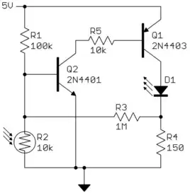
I was the one that posted the circuit you refer to in your question.
The basic problem is that you monkeyed around with something without understanding how it works. According to the description, here is the mess you ended up with:
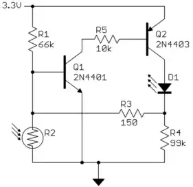
This clearly isn't going to do what you want. The very high R4 is basically not there, and what you have is a latching circuit, as demonstrated in your video.
R4 should be sized so that it supports the LED current you want. Let's say this is a 20 mA green LED that drops about 2.1 V. Figure 200 mV accross Q2 when on, so that leaves 1.0 V accross R4. 1.0 V / 20 mA = 50 Ω. A 56 Ω resistor would be good, or maybe 51Ω if you really want the last bit of brightness and are willing to live on the edge.
Next you have to find what the resistance of the LDR is at the light level you want the circuit to switch at. I think that was determined to be 10 kΩ in the original question, so I'll use that as example. LDRs are available over a wide range, so this is something you either have to know from the datasheet for your particular LDR, or you have to measure it.
In any case, you want hte R1-R2 voltage divider to produce whatever voltage it takes to just turn on Q1. Let's say 550 mV since the current to turn on Q1 to cause positive feedback thru Q2 and R3 is quite small. Experiment to find the actual threshold. If R2 is 10k Ω then R1 must be 50 kΩ given the conditions we somewhat arbitrarily picked above. Your 66 kΩ value is therefore in the right ballpark, again assuming the LDR will be around 10 kΩ at the light threshold level. You'll have to adjust R1 to the desired light threshold level by experimentation anyway.
R5 is just there to limit the maximum current thru Q1 and thru the base of Q2. You want that to be a bit more than what it takes to keep Q2 saturated while maintaining the LED current. Let's say Q2 can be counted on to have a gain of 50. With the LED current set to 20 mA, that means you need at least 400 µA out of the base of Q2, although 50% more would be good. Figure the B-E drop of Q2 is 750 mV, and Q1 drops 200 mV. That leave 2.35 V accross R5. 2.35 V / 400 µA = 5.9 kΩ. I'd probably use 4.3 kΩ
That leaves R3. The circuit will work without R3. There is fairly high gain around the threshold point, but of course that gain is not infinite. There will be a range of light levels over which the LED will go from off to fully on. The purpose of R3 is to provide some positive feedback so that the circuit has snap action, or hysteresis. There are ways to calculate this, but this is getting long already. I'd start at 1 MΩ and keep reducing it by a factor of around 2 until you get the level of hysteresis you want. If you get down to 100 kΩ and you still don't get enough hysteresis, something else is probably wrong. Your value of 150 Ω is totally inappropriate (I can't even begin to imagine how you thought changing the original value by 7000 was a good idea) and will make the hystersis effect dominate and the light level become essentially irrelevant. What you end up with is just a latch, as your video demonstrated.