7

I've designed an RS232-to-TTL converter board based on TI's MAX232 IC that I plan to use to program a few custom Arduino boards that I have. However, I'm having trouble with the board and I'm hoping that someone can help me debug it.

First, let me show you my setup, below.

My setup

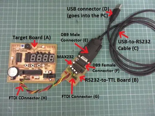
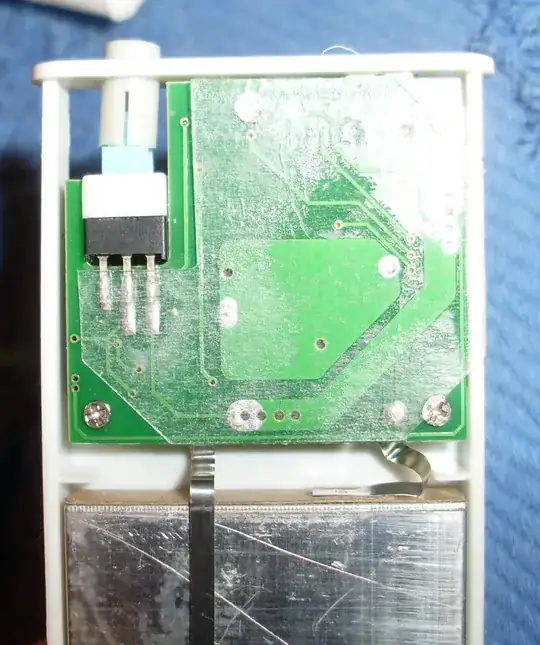
Here's a brief description of what's in the picture:

  • Target Board (A): it's a custom standalone ATmega328P board (a clock) that I intend to program using serial programming and the Arduino IDE. It's connected to the Board B through a FTD-like cable through Connector (H).

  • RS232-to-TTL Converter Board (B): it's the MAX232 based RS232-to-TTL converter board I designed and am trying to debug. It's the main topic of this question. It's connected to the Target Board (A) with the FTDI-like cable through Connector (G) and to the USB-to-RS232 Cable (C) through a Female DB9 Connector (F).

  • USB-to-RS232 cable (C): I don't have a proper COM port on my PC, so that's what I use to get a Serial Port instead. It's connected to the PC through an USB connector (D) and to the Board B through a Male DB9 Connector (E).

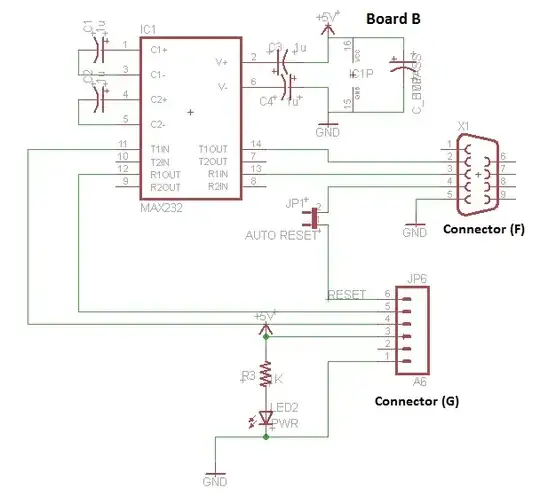
The schematics of Board B are below.

RS232-to-TTL converter board (B)

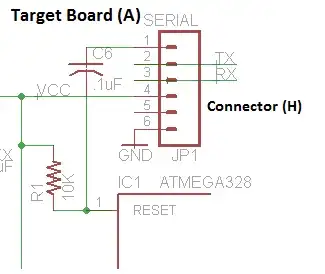
The programming header schematics on Target Board (A) is shown below.

ATmega328P serial programming header on Target Board (A)

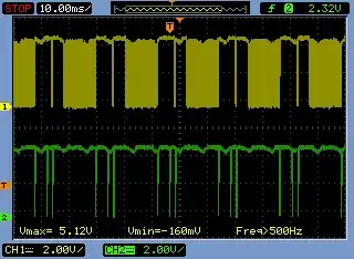
First thing I realized is that the USB-to-RS232 Cable (C) is of the cheap kind. Instead of delivering RS232 standard signal levels in the -12V/+12V range, it delivers 0V/5V instead. I figured that using the following test: I connected the USB-to-RS232 Cable (C) to the PC and disconnected Male DB9 Connector (E) from the Converter Board (B) and probed pin 3 from the Male DB9 Connector (E) while I was sending a series of ASCII char 'A' through the serial monitor. Below is the scope shot resulting of this test.

Characterization of USB to RS232 cable signal

Incidentally, I've noticed that the various MAX232 IC's made by various vendors are designed to cope with this violation of RS232 signal levels and accept 0V/5V signals as well. Below are two scope shots that I used to prove it. In the first shot I applied a 0V/5V square wave into MAX232 pin 13 (while inserted and powered by my converter board) with my homemade function generator (noisy, yes) - that's the yellow trace - and checked the output of pin 12 (TTL level RX - green trace). To my surprise, TI's MAX232 respond with the correct TTL signals. The second shot is a correct RS232 -6V/+6V signal simulated by a square wave I inserted into the same pin. Both yield the same results.

enter image description here enter image description here

I did some other measurements on my Converter Board (B) to the point I was satisfied with it. For example, pin 2 on MAX232 shows +9.5V while pin 6 shows -9.5V. The scope shows the voltage doubler and inverter are working fine as well, with a nice and steady 40kHz square wave in each case. I've also applied 0/5V square wave of about 68kHz to pin 10 of the MAX232 and scoped pin 7 of MAX232. I got a nice and clean inverted -6V/+6V RS232 signal (images not shown here).

Then I tested serial monitor echo shorting the TX/RX pins at various points. The results where:

  1. Without MAX232 IC in its socket I shorted pins 2 and 3 on DB9. Echo ok.
  2. Placed MAX232 IC on the board and shorted its pins 11 and 12. Echo ok.
  3. With ATmega328P off its socket, I shorted pins 2 and 3. Echo ok.

Then I connected the setup to program my ATmega328P Target Board (A). The avr-dude output is shown at the end of this post. Below is a summary with just the error message:

...
avrdude: stk500_getparm(): (a) protocol error, expect=0x14, resp=0x90
...
avrdude: stk500_cmd(): protocol error

During this programming attempt, I measured the signals below. The yellow trace is data being sent to the MCU while the green trace is data being received by it:

enter image description here

When I get the error, there's a sudden interruption in the communication. From one attempt to the next, the problem happens at different points during communication.

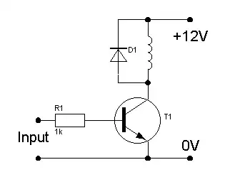
Finally, I replaced my MAX232 board with an older one that I have, that uses the transistor trick instead of the MAX232 IC, and all starts to work properly. With the old board I can get the target board programmed. Below is the scope shot showing the successful communication during programming of the target board in this case.

enter image description here

I'm certainly overlooking something, but I cannot tell what it is. So my question is: what's wrong with my setup? What else can I check or measure to figure out the problem?

Here's the Arduino IDE and avr-dude output:

Binary sketch size: 9.946 bytes (of a 32.256 byte maximum)
C:\Users\Ricardo\Documents\arduino-1.0.5\hardware/tools/avr/bin/avrdude -CC:\Users\Ricardo\Documents\arduino-1.0.5\hardware/tools/avr/etc/avrdude.conf -v -v -v -v -patmega328p -carduino -P\\.\COM5 -b115200 -D -Uflash:w:C:\Users\Ricardo\AppData\Local\Temp\build2465731745810216807.tmp\DefusableClock_v2.cpp.hex:i 

avrdude: Version 5.11, compiled on Sep  2 2011 at 19:38:36
         Copyright (c) 2000-2005 Brian Dean, http://www.bdmicro.com/
         Copyright (c) 2007-2009 Joerg Wunsch

         System wide configuration file is "C:\Users\Ricardo\Documents\arduino-1.0.5\hardware/tools/avr/etc/avrdude.conf"

         Using Port                    : \\.\COM5
         Using Programmer              : arduino
         Overriding Baud Rate          : 115200
avrdude: Send: 0 [30]   [20] 
avrdude: Recv: . [14] 
avrdude: Recv: . [10] 
         AVR Part                      : ATMEGA328P
         Chip Erase delay              : 9000 us
         PAGEL                         : PD7
         BS2                           : PC2
         RESET disposition             : dedicated
         RETRY pulse                   : SCK
         serial program mode           : yes
         parallel program mode         : yes
         Timeout                       : 200
         StabDelay                     : 100
         CmdexeDelay                   : 25
         SyncLoops                     : 32
         ByteDelay                     : 0
         PollIndex                     : 3
         PollValue                     : 0x53
         Memory Detail                 :

                                  Block Poll               Page                       Polled
           Memory Type Mode Delay Size  Indx Paged  Size   Size #Pages MinW  MaxW   ReadBack
           ----------- ---- ----- ----- ---- ------ ------ ---- ------ ----- ----- ---------
           eeprom        65    20     4    0 no       1024    4      0  3600  3600 0xff 0xff
                                  Block Poll               Page                       Polled
           Memory Type Mode Delay Size  Indx Paged  Size   Size #Pages MinW  MaxW   ReadBack
           ----------- ---- ----- ----- ---- ------ ------ ---- ------ ----- ----- ---------
           flash         65     6   128    0 yes     32768  128    256  4500  4500 0xff 0xff
                                  Block Poll               Page                       Polled
           Memory Type Mode Delay Size  Indx Paged  Size   Size #Pages MinW  MaxW   ReadBack
           ----------- ---- ----- ----- ---- ------ ------ ---- ------ ----- ----- ---------
           lfuse          0     0     0    0 no          1    0      0  4500  4500 0x00 0x00
                                  Block Poll               Page                       Polled
           Memory Type Mode Delay Size  Indx Paged  Size   Size #Pages MinW  MaxW   ReadBack
           ----------- ---- ----- ----- ---- ------ ------ ---- ------ ----- ----- ---------
           hfuse          0     0     0    0 no          1    0      0  4500  4500 0x00 0x00
                                  Block Poll               Page                       Polled
           Memory Type Mode Delay Size  Indx Paged  Size   Size #Pages MinW  MaxW   ReadBack
           ----------- ---- ----- ----- ---- ------ ------ ---- ------ ----- ----- ---------
           efuse          0     0     0    0 no          1    0      0  4500  4500 0x00 0x00
                                  Block Poll               Page                       Polled
           Memory Type Mode Delay Size  Indx Paged  Size   Size #Pages MinW  MaxW   ReadBack
           ----------- ---- ----- ----- ---- ------ ------ ---- ------ ----- ----- ---------
           lock           0     0     0    0 no          1    0      0  4500  4500 0x00 0x00
                                  Block Poll               Page                       Polled
           Memory Type Mode Delay Size  Indx Paged  Size   Size #Pages MinW  MaxW   ReadBack
           ----------- ---- ----- ----- ---- ------ ------ ---- ------ ----- ----- ---------
           calibration    0     0     0    0 no          1    0      0     0     0 0x00 0x00
                                  Block Poll               Page                       Polled
           Memory Type Mode Delay Size  Indx Paged  Size   Size #Pages MinW  MaxW   ReadBack
           ----------- ---- ----- ----- ---- ------ ------ ---- ------ ----- ----- ---------
           signature      0     0     0    0 no          3    0      0     0     0 0x00 0x00

         Programmer Type : Arduino
         Description     : Arduino
avrdude: Send: A [41] . [80]   [20] 
avrdude: Recv: . [14] 
avrdude: Recv: . [83] 
avrdude: Recv: . [10] 
avrdude: Send: A [41] . [81]   [20] 
avrdude: Recv: . [14] 
avrdude: Recv: . [84] 
avrdude: Recv: . [10] 
avrdude: Send: A [41] . [82]   [20] 
avrdude: Recv: . [14] 
avrdude: Recv: . [04] 
avrdude: Recv: . [90] 

avrdude: stk500_getparm(): (a) protocol error, expect=0x14, resp=0x90
avrdude: Send: A [41] . [98]   [20] 
avrdude: Recv: . [14] 
avrdude: Recv: . [03] 
avrdude: Recv: . [10] 
         Hardware Version: 131
         Firmware Version: 132.1077487570
avrdude: Send: A [41] . [84]   [20] 
avrdude: Recv: . [14] 
avrdude: Recv: . [03] 
avrdude: Recv: . [10] 
avrdude: Send: A [41] . [85]   [20] 
avrdude: Recv: . [14] 
avrdude: Recv: . [03] 
avrdude: Recv: . [10] 
avrdude: Send: A [41] . [86]   [20] 
avrdude: Recv: . [14] 
avrdude: Recv: . [03] 
avrdude: Recv: . [90] 

avrdude: stk500_getparm(): (a) protocol error, expect=0x14, resp=0x90
avrdude: Send: A [41] . [87]   [20] 
avrdude: Recv: . [14] 
avrdude: Recv: . [03] 
avrdude: Recv: . [10] 
avrdude: Send: A [41] . [89]   [20] 
avrdude: Recv: . [14] 
avrdude: Recv: . [83] 
avrdude: Recv: . [10] 
         Vtarget         : 0.3 V
         Varef           : 0.3 V
         Oscillator      : 921.600 kHz
         SCK period      : 142.2 us

avrdude: Send: A [41] . [81]   [20] 
avrdude: Recv: . [14] 
avrdude: Recv: . [04] 
avrdude: Recv: . [10] 
avrdude: Send: A [41] . [82]   [20] 
avrdude: Recv: . [14] 
avrdude: Recv: . [04] 
avrdude: Recv: . [10] 
avrdude: Send: B [42] . [86] . [00] . [00] . [01] . [01] . [01] . [01] . [03] . [ff] . [ff] . [ff] . [ff] . [00] . [80] . [04] . [00] . [00] . [00] . [80] . [00]   [20] 
avrdude: Recv: . [14] 
avrdude: Recv: . [10] 
avrdude: Send: E [45] . [05] . [04] . [d7] . [c2] . [00]   [20] 
avrdude: Recv: . [14] 
avrdude: Recv: . [10] 
avrdude: Send: P [50]   [20] 
avrdude: Recv: . [14] 
avrdude: Recv: . [10] 
avrdude: AVR device initialized and ready to accept instructions

Reading | avrdude: Send: u [75]   [20] 
avrdude: Recv: . [14] . [1e] . [95] . [0f] . [10] 
################################################## | 100% 0.00s

avrdude: Device signature = 0x1e950f
avrdude: Send: V [56] . [a0] . [03] . [fc] . [00]   [20] 
avrdude: Recv: . [14] 
avrdude: Recv: . [00] 
avrdude: Recv: . [10] 
avrdude: Send: V [56] . [a0] . [03] . [fd] . [00]   [20] 
avrdude: Recv: . [14] 
avrdude: Recv: . [00] 
avrdude: Recv: . [10] 
avrdude: Send: V [56] . [a0] . [03] . [fe] . [00]   [20] 
avrdude: Recv: . [14] 
avrdude: Recv: . [00] 
avrdude: Recv: . [10] 
avrdude: Send: V [56] . [a0] . [03] . [ff] . [00]   [20] 
avrdude: Recv: . [14] 
avrdude: Recv: . [00] 
avrdude: Recv: . [90] 
avrdude: stk500_cmd(): protocol error
Ricardo
  • 6,134
  • 19
  • 52
  • 85
  • 6
    Nicely documented. – tcrosley Mar 28 '14 at 03:50
  • @tcrosley Thanks! I tried my best, but there were still some obscure points that I tried to clarify with my last edit. – Ricardo Mar 28 '14 at 12:12
  • 2
    Is there a reason the "reset" line is at RS232 voltages and not run through the converter? Does the Arduino need a higher voltage to program or something? – markrages Mar 28 '14 at 14:47
  • @markrages - that's a good point. I don't know. I completely missed it. I'll try and dig up where that design comes from, or if it's my own *creativity*. – Ricardo Mar 28 '14 at 15:01
  • 1
    While the reset circuit you have *might* be able to absorb the voltage of the RS232 driver without damage, a perhaps overlooked issue is that RS232 drivers and receivers traditionally **invert**. So the logic of the reset line may be backwards from what the software expects. You have an unused receiver channel, perhaps you should use that. Also make sure the software is driving the one of the RTS or DTR possibilities that you are wired for. If you can pre-program a sketch that would interact on the serial you can do some additional validation. – Chris Stratton Mar 28 '14 at 15:16
  • @ChrisStratton - Of all things in my board, the reset is the only one that works (at least apparently). The Arduino IDE seems to successfully reset the board before and after a firmware upload. But, yes, I haven't considered the fact that the RS232 reset voltage may have damaged my MCUs. I'll look into that. Using the 2nd driver is a good idea for that! Thanks! – Ricardo Mar 28 '14 at 15:28
  • With an inverted signal, I'd expect it would still reset, but at the wrong time (how wrong would depend on when the signal is driven in what normally is the inactive direction, which with inversion would become the active one). – Chris Stratton Mar 28 '14 at 15:31
  • @ChrisStratton - According [this Wikipedia article on RS232](http://en.wikipedia.org/wiki/RS-232#Voltage_levels), the control signals have opposite polarity of the data signals, so reset (DTR) isn't inverted. But the levels may still hurt the MCU. – Ricardo Mar 28 '14 at 17:01
  • @Ricardo - they are still electrically inverted when they go through the line driver or receiver, it is just that their active sense is opposite of the data lines. Avrdude already knows it has opposite sense, but it's going to expect it to be inverted in the level translator the same as the others. – Chris Stratton Mar 28 '14 at 17:05
  • @ChrisStratton - Point taken. But I haven't seen the reset line going trhough the inverter on the various MAX232 designs I've found. I'll do some more research as I'm worried about the reset voltage I'm applying to my MCUs. – Ricardo Mar 28 '14 at 17:28
  • 1
    See for example http://www.ftdichip.com/Support/Documents/DataSheets/Cables/DS_UC232R.pdf where the data and status lines go through identical channels of the level converter. I believe when people use that USB-serial chip with an Arduino and no level shifting, they don't invert the reset, so when it's gone through one inverter in the level shifter of your cable it will need to go through another in your circuit or else it will end up opposite of its usual sense. – Chris Stratton Mar 28 '14 at 17:32

2 Answers2

2

You say you scoped pin 3 of the DB9 and saw 0-5V. Pin 3 is receive data from the outside world, and is driven by your USB-to-TTL serial cable.

The MAX232 receives RS-232 levels on pins 8 and 13, converting them to TTL levels on pins 9 and 12, respectively. The MAX232 receives TTL levels on pins 10 and 11, driving RS-232 levels on pins 7 and 14, respectively.

To paraphrase Dr. Indiana Jones, the noted professor of archaeology, you're looking at the wrong pins.

Run a simple 555 pulse train generator off of +5, apply it to pin 10 of the MAX232 (not connected on your schematic), scope pin 7 of the MAX232, and see what you get.

John R. Strohm
  • 2,621
  • 14
  • 16
  • Sorry, I may have not been clear enough. I don't have a USB-to_TTL serial cable. I'm trying to simulate one by using a USB-to-RS232 cable connected to this RS232-to-TTL converter I made. – Ricardo Mar 28 '14 at 02:23
  • In the check you mentioned in your first paragraph, I connected the USB-to-RS232 cable to my computer and left the DB2 unconnected. Then I probed pin 3 while sending data through the terminal. Then I got the 0V/5V signal and concluded that the cable doesn't follow RS232 standards. According to [this picture](http://www.usconverters.com/images/rs232-pinout.jpg), pin 3 is TXD on the male DB9 connector. Or am I just confused? – Ricardo Mar 28 '14 at 02:23
  • So, pin 3 on male DB9 is transmit data from the computer and drives data into the RS232-to-TTL converter, right? It's the opposite of what you said in your first paragraph. – Ricardo Mar 28 '14 at 02:24
  • Also, I've done what you suggested on the last paragraph of your answer. I applied 0/5V square wave of about 68kHz to pin 10 of the MAX232 and scoped pin 7 of MAX232. I got a nice and clean inverted -6V/+6V RS232 signal. – Ricardo Mar 28 '14 at 02:27
  • @Ricardo, OK, that means that the transmit side is working. Now, you need to apply a +12V/-12V (nominal: +6V/-6V should work) square wave to pin 3 of the DB9 or pin 13 of the MAX232, and verify TTL square wave on pin 12. The easiest way to do this is leave the TTL square wave on pin 10 of the MAX232, short pins 2 and 3 of the DB9 connector, and scope pin 12. – John R. Strohm Mar 28 '14 at 04:48
  • Pin 3 of the DB9 connector, the way you have it wired, is expecting to receive a +12/-12 RS-232 signal from somewhere else in the universe, something NOT SHOWN on your schematic. This gets into the whole DCE/DTE thing that made RS-232 interfacing a nightmare, and created the market for gazillions of RS-232 breakout boxes, null modems, and gender benders. Things got better when the IBM PC effectively standardized the connectors for everyone. – John R. Strohm Mar 28 '14 at 04:51
  • The problem with that picture is that it doesn't tell you the single most important thing you must understand about RS-232. There are TWO (2) connectors involved in any RS-232 connection, a male and a female. On ONE of them (and I can't remember which), pin 2 drives and pin 3 receives. On the other one, which is connected to the other device, pin 2 receives and pin 3 drives. That way, when you plug the two devices together, you are always connecting a driver pin to a receiver pin, and vice versa. Connecting a driver pin to a driver pin is a good way to burn out a driver. – John R. Strohm Mar 28 '14 at 04:56
  • 1
    @JohnR.Strohm However the OP said he was able to short pins 11 and 12 on the MAX232, and connect the MAX232 to a cable coming from a PC using the DB9. That means the DB9 *has* to be wired correctly, or the transmitter/receiver in the MAX232 wouldn't be connected to the TX/RX pins on the DB9 properly. – tcrosley Mar 28 '14 at 05:29
  • @JohnR.Strohm I agree with tcrosley that my DB9 connection is correct, but it looks like I didn't present my setup as clearly as possible. So I tried to clarify some points with my last edit. Please check it out. – Ricardo Mar 28 '14 at 12:14
  • Am I missing something here? The cable you have does RS232 protocol, but with 0v/5v in stead of +/-12v, right? That's what we call 'TTL' and is exactly what you should be able to hook directly up to the ATMega. No MAX 232 required... The MAX 232 converts from 0/5 to -12/+12, but the ATMega needs 0/5 (unless it's a 3.3v device, but I think even then 0/5v will still be ok). So I'd start by hooking RX to TX and TX to RX, straight from the DB9 to the ATMega/FTDI connector (don't forget ground too) and try again. – RJR Mar 28 '14 at 12:56
  • @RJR - The cable is supposed to output RS232 but outputs 0v/5V instead of +/-12V. It's not TTL because it's output is inverted. I didn't know such thing existed until I read [this answer](http://electronics.stackexchange.com/a/24194/29792). Apparently, cheap cables use the 5V USB power supply directly to produce output and the MAX232 and its various clones accept it. I checked Maxim's MAX232 as well as the clones ICL232 and HIN232 and they all say that they accept the incorrect 0V/5V RS232 input. TI's datasheet seem to comply to +/-3V limits, but under my scope, it also accepts the 0V/5V. – Ricardo Mar 28 '14 at 13:06
  • @RJR - So, I cannot use that cable to program my ATmega328P directly (because the 0V/5V is inverted), unless I invert the signal some other way, not using MAX232. – Ricardo Mar 28 '14 at 13:08
  • Ah, yes, that would be a problem. You can invert the TTL with a couple of transistors easiy though (or use an invertor IC). Just google 'TTL transistor inverter' for the scematic. – RJR Mar 30 '14 at 00:31
  • If your cable has FTDI chip inside you should be able to run configuration program for it. In there you can invert any line, I believe. – Maple May 31 '18 at 15:53
  • @Maple, unless your cable has a known authentic FTDI chip inside of it, as opposed to a cheap counterfeit, you are going to have all kinds of headaches with drivers for the cable. FTDI got sick and tired of the counterfeiters stealing their business, and taught their drivers to recognize the genuine chips and refuse to work with counterfeits. This caused no end of trouble for the Chinese handi-talkie customers, because the programming cable manufacturers bought the counterfeit chips. (I am one of the guys who had trouble, as is my brother!) – John R. Strohm May 31 '18 at 17:58
2

Your question was way to long to read, but it seems you are having some problems with a MAX232-type of converter circuit. I have made what seems to be a very similar circuit using one of the TI variants of the chip, and even sell it as a product. Go to www.embedinc.com/products/rslink2 and you can see all the documentation, from a picture to the board layout to the schematic. Perhaps you can see what you are doing differently.

One thing I noticed while skimming your question is that you are using electrolytic caps. Double check that the polarity of each is correct. Another issue is that some COM ports, particularly USB to RS-232 converters, won't work without RTS/CTS, whether this is enabled in software or not. Note how I have pins 7 and 8 connected to each other on the DB9-F connector.

Olin Lathrop
  • 310,974
  • 36
  • 428
  • 915
  • 1
    I didn't know how to shorten the question as I don't know where the problem is. So I decided to show all I have in detail. – Ricardo Mar 28 '14 at 13:15
  • Also, while studying the subject, I did come across your product page and the schematics linked from there. Really nice! But I didn't study it in more detail because the IC you used didn't seem pin compatible with mine. But I'll take a closer look. Thanks for your help! +1 – Ricardo Mar 28 '14 at 13:18
  • This is the closest to an answer that I got on this, so I'm accepting it. Thanks!! I've narrowed down the problem: it relates to an increase in errors (due to noise or crystal sync) at 115200 bps, that do not occur at 57600 bps. See [my other question for details](http://electronics.stackexchange.com/q/104901/29792). – Ricardo Apr 01 '14 at 12:15