3

I'm trying to make this simple code lock circuit, and I ordered this keyboard for it.

Keyboard

However, there isn't any kind of manual for it, and I simply don't understand how it works.

Here's a larger picture of it (sorry for the horrible soldering, I've a bad solder, and I probably do it wrong also.)

enter image description here

So there's 7 wires on it currently, but how do I actually use this thing?

Ricardo
  • 6,134
  • 19
  • 52
  • 85
  • Looks like a bog-standard matrix keypad to me. – Ignacio Vazquez-Abrams Mar 21 '14 at 15:15
  • @IgnacioVazquez-Abrams Well, if I want to hook it into 12 LEDs and have one led light up on keypress, what would I do? :) –  Mar 21 '14 at 15:19
  • Use a MCU to scan it. – Ignacio Vazquez-Abrams Mar 21 '14 at 15:19
  • 1
    Or use a 4017 and an oscillator to scan the keyboard, with a few (like 7) transistors and resistors to drive the 12 LEDs. – Spehro Pefhany Mar 21 '14 at 15:28
  • 1
    @Christian, [here are a few good links](https://www.google.com.br/search?q=how+to+solder&rls=com.microsoft:pt-BR:IE-Address&ie=UTF-8&oe=UTF-8&sourceid=ie7&rlz=1I7SAVR_pt-BRBR533&gfe_rd=cr&ei=zl8sU_gG6d3yB6m5gVg) on how to improving your soldering skills. – Ricardo Mar 21 '14 at 15:51
  • @Ricardo Very funny ;) I just need a pair of new hands and a better solder :) –  Mar 21 '14 at 15:53
  • I hope I didn't offend you by posting those links. Seriously. I just thought they would be useful. I didn't think your soldering was that bad, anyway. Soldering wires is a bit harder than component leads in a PCB. But similar soldering videos really helped me a lot, so I thought I would show them to you in case you haven't seen them yet. – Ricardo Mar 21 '14 at 15:55
  • @Ricardo No, of course you didn't :) I know the basics but my hands are way too shaky today! –  Mar 21 '14 at 16:02

3 Answers3

7

There are four rows and three columns which make a matrix of 12 possible connections. Each switch is located at one of the cross-points of the columns and rows: -

enter image description here

If you "read" the value of the voltages on a single column and activate each row with a positive voltage (not together but in turn) you can deduce which of the four switches is pressed in that column.

Read the voltage for each of the three columns and you can deduce which button is pressed of the 12. Two buttons being pressed can confuse things so be aware of that.

Andy aka
  • 434,556
  • 28
  • 351
  • 777
  • (I edited the big picture, there's numbers on it now). So, I put `+` power the pin 1 (see the picture above), and started to try out the pins on the LED. So the LED has `-` on the catode. I connected pin 2 on the anode of the LED, and started pressing buttons. Number 2 worked. Pin 3 did nothing, no matter of what button I pressed. So I tested them all, and I managed to light the LED with keys 2,5,8 & 0. With power on the pin 1. –  Mar 21 '14 at 15:43
  • @Christian - sounds like you are getting there - the pin numbers on the picture in my answer - don't expect they'll match your keyboard so take that info with a pinch of salt!! – Andy aka Mar 21 '14 at 15:48
  • You know what. Pin 2 + Pin 3 + pressing 1 on the keypad lighted the LED. And Pin 1 + Pin 2 + pressing 2 on the keypad lighted the LED. Guess what Pin 5 + Pin 2 + pressing 3 did? –  Mar 21 '14 at 15:59
  • So that pins 1,3 and 5 are hooked to the power, that leaves me with 4 pins and 12 buttons. How do I know which button is pressed? –  Mar 21 '14 at 18:44
  • You have to set a 5V on pin 3 with 0V on 1 and 5 and read pins 2, 4, 6 and 7 - this tells you which (if any) buttons are pressed in the first column. Then you repeat the procedure with 5V on pin 1 and 0V on 3 and 5. Repeat for 5V on pin 5 with 0V on 3 and 1 and you have read three results that would normally be all 0,0,0,0 unless a button is pressed then you will find a 1 in one of the results - that tells you the position of the button that is pressed. It needs some form of logic to do this quickly so there is zero latency to the user. – Andy aka Mar 21 '14 at 19:17
  • How would I actually do this? Do I need some extra parts? –  Mar 21 '14 at 19:24
  • Ahhhh, I've just followed the link to what you are trying to do and there is no relatively simple and convenient way this will work for you. You actually do need a keyboard where 13 wires come out or all twelve switches are not connected as rows and columns. Having said that, the design only needs 5 switches and they all share a common line so you could use column 1, 2 or 3 to get you 4 of the switches needed, but you'll need an extra switch (say for the reset line). – Andy aka Mar 21 '14 at 19:43
  • Yeah I know I only need four, but it would be nice if it actually required a certain code and not a certain order ;) As now I get the same result with 3 different choices. What would it require to make it work? As it will probably be easier than finding a keyboard that takes 13 wires instead of these 7. At least here. –  Mar 21 '14 at 19:59
2

Most likely the keys are arranged in a matrix, which explains 7 wires nicely. There is one wire for each column and one wire for each row. The keyboard may be as primitive as each key simply shorting its row and column lines together. Or, it could connect them with a diode.

Probe around with a ohmmeter and you should be able to figure out what column and row each lead is connected to. Or, try probing with a 5 V supply, LED, and 2.7 kΩ (about) resistor in series. That will put 1-2 mA thru the led when the two ends are shorted. That will be dim, but should still be visible in normal office lighting. Whatever is in the keypad should not be hurt by 5 V or 2 mA.

Olin Lathrop
  • 310,974
  • 36
  • 428
  • 915
  • Well, I don't happen to own a multimeter (yet), but 5V, LED and a resistor shouldn't be a problem. But how do I do it? `+` to one of the wires, `-` to the another end of the LED and one wire to the anode of the LED and to the keyboard itself? –  Mar 21 '14 at 15:24
1

If you decide to use an MCU to scan the keypad, below is a polling algorithm that you can use (which I extracted from this source). It took me a while to understand it (had to read it twice), but once I did, it helped me A LOT.

Continuous Polling Operations

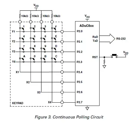
In this mode of operation, the MicroConverter continuously polls the keypad for a key press. This operation is used where the MicroConverter has completed a task and is now waiting for input before proceeding. In this mode, the keypad is connected to one port of the MicroConverter, Port 2 in this example. Figure 3 shows the connectivity. The output from the MicroConverter, following a key press, is viewed using HyperTerminal running on a PC. The MicroConverter is connected to the PC via the COM1 port. This is the reason for showing the RS-232 connection.

As can be seen in Figure 3, the four columns (X1 to X4) are pulled up to VDD and are also connected to four of the MicroConverter port pins (P2.4 to P2.7). The four ADuC8xx rows (Y1 to Y2) are connected to the other four port pins (P2.0 to P2.3). The MicroConverter outputs 0 or drives low the keypad rows (P2.0 to P2.3) one at a time and checks the columns (P2.4 to P2.7) for a low condition.

For example, the following is the sequence of events up to a switch press detection (Switch 5 in this case). The MicroConverter outputs a low on P2.0 (Y1) and checks for a low on P2.4 to P2.7. In this case, no low is found and so it returns P2.0 (Y1) to high and moves on to P2.1 (Y2). The MicroConverter now drives P2.1 (Y2) low and again checks P2.4 to P2.7 for a low condition. This time it finds that P2.5 (X2) is low, due to Switch 5 being pressed. The MicroConverter now knows that the interconnect of Y2 and X2 has been shorted, therefore, this is 5.

X-Y keypad arrangement

If you have an Arduino handy, you don't need to implement the algorithm yourself. Instead you can use the Arduino Keypad lib. The links are below:

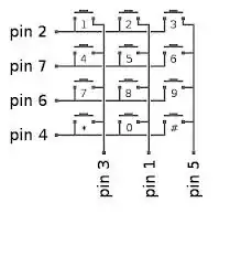
See more details (on how the keypad is internally wired, for example) here in my other related answer

Ricardo
  • 6,134
  • 19
  • 52
  • 85