0

I have the following setup:

schematic

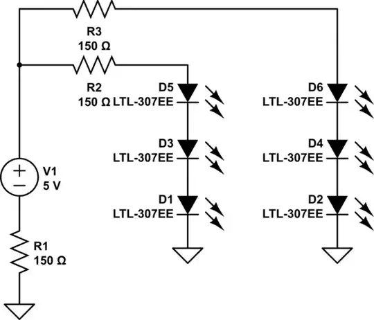
simulate this circuit – Schematic created using CircuitLab

(The LEDs are actually some generic UV leds without a known part number, so I didn't edit the default number in the schematic.)

When applying 5 to 10 Volts at V1 I always only get D1 to glow, how can that be and what can I do to fix this?

Already checked the board for shorts and also supplied 5V directly to some other LEDs by crocodile clip cable, then they work correctly.

Oh and sometimes when using crocodile clip cable to jump over R1 some other LEDs randomly flash on, and then instantly off, and D1 remains the only one glowing.

JYelton
  • 32,302
  • 33
  • 134
  • 249
nonchip
  • 187
  • 10
  • Possibly the other ones are all fried. What happens when you power them individually through an appropriate resistor? – Spehro Pefhany Mar 20 '14 at 20:50
  • Some of the things you describe doing could be fatal to the LEDs, so maybe the ones that don't like are now internally shorted. Then there are more things that don't make sense. 3 UV LEDs in series would require more than 5 V to light. They are usually over 3 V each. Also, if they really are UV LEDs, then how can you tell they aren't lighting if you're just looking at them? – Olin Lathrop Mar 20 '14 at 21:01

1 Answers1

1

If the LEDs are fully within the UV spectrum, you won't see any visible light emitted from them, except for cases where the LED is being overdriven with too much current, etc.

If these are "blacklight" LEDs then they're a deep purple with some UV, and you should be able to see visible light from them.

Assuming that these are typical 20mA If LEDs with a Vf of ~3.2 volts, you could try connecting just one of them in series with a 90Ω resistor (100Ω is the closest common value). Do this for all of your LEDs to ensure that they work.

Once you've established that they are all functional, you can go back to your series-parallel circuit. However three LEDs in series will require 3 \$\cdot\$ 3.2V = 9.6V. This means you'll need to provide at least 9.6V prior to selecting current-limiting resistors for each branch.

If you want to use 5V, consider connecting the LEDs in parallel such that they each have a 90-100Ω current-limiting resistor.

Remove R1, the 150Ω resistor from the battery to ground; it serves no purpose.

JYelton
  • 32,302
  • 33
  • 134
  • 249
  • they are not fully in UV, more like blacklight. i just double checked all LEDs, they work. now I'll try your other suggestions. or most of them. don't really want to desolder them – nonchip Mar 20 '14 at 21:01
  • just did some tests with one of the LEDs on the breadboard, verified that i was just below the required voltage, so D1 glowing was random luck i guess – nonchip Mar 20 '14 at 21:07
  • 1
    @nonchip LEDs will vary somewhat; the datasheet for a typical LED will provide a *range* for Vf rather than a single value. Those LEDs might be something like 2.8-3.4V or whatever. It's also possible you have a damaged one that is well below spec. – JYelton Mar 20 '14 at 21:09
  • @nonchip Random luck does not explain it. If they are truly in series they should see the same current and be of broadly similar brightness. Something else is going on such as a short from D1 anode to R2. – Spehro Pefhany Mar 20 '14 at 22:33
  • got it working now by putting them all in parallels. – nonchip Mar 21 '14 at 10:27
  • 1
    @nonchip Sounds good. Just make sure they each have a current-limiting resistor when in parallel. Otherwise they may share current unequally which can result in failure of one that accelerates to others. Refer to [this question](http://electronics.stackexchange.com/q/22291/2028) for more information. – JYelton Mar 21 '14 at 16:54
  • of course, don't worry :) – nonchip Mar 21 '14 at 22:03