7

I am looking for a algorithm that can detect the rate of symbols in a base-band signal.

The Gardner method is a way to cancel out the timing drift and synchronize the receiver to sender when the symbol rate (number of samples per symbol) is known. The MATLAB also provides a package which implements Gardner method.

But what if we don't know the symbol rate? I found some proposed methods like using cyclostationary properties of signals.

Is there any package/implementation of these methods (or any other method) in MATLAB or C symbol rate estimation?


Update #1:

This is a simple implementation which uses cyclostationary properties to estimate baud rate, but it is not suitable for large inputs like wave files.


Update #2:

After demodulating and filtering the received signal I have a basedband signal like: enter image description here

Symbols are encoded as different shapes in this signal (e.g. different levels of voltage if the sender uses square shape filter). As we can see, the highest frequency in this signal is not the symbol-rate.

I am not seeking for a new solution/idea to estimate symbol rate. I am looking for an implementation of a known method (like cyclostationary-based or wavelet-based methods) for symbol rate estimation.

Isaac
  • 171
  • 2
  • 7
  • What is your signal look like at baseband? Is it a square wave? – Kellenjb Feb 17 '11 at 15:59
  • It is a baseband signal. It is filtered raised cosine filter. And it has some white Gaussian noise. – Isaac Feb 17 '11 at 16:03
  • Sounds nasty to me. What type of system is using this? – Kellenjb Feb 17 '11 at 17:01
  • As a note, I have been talking through this with my coworker. At least from the theory that we remember being taught we thought that you don't get any benefit from using shapes other then square. – Kellenjb Feb 17 '11 at 17:18
  • What kind of modulation is used? BTW: I thought that in general baseband signal is down covered by mixer but not yet demodulated. Is this a case? – mazurnification Feb 17 '11 at 17:21
  • It is a signal a from a radio communication system. Using square shape signal minimizes the probability of misdetection of symbol, But square shapes needs a wide bandwidth to send. The raised cosine shape provides a good trade-off between bandwidth and symbol detection. Signals would be modulated with BPSK, QPSK, etc. The modulation does not have direct impact on symbol rate detection because the given signal is demodulated already. – Isaac Feb 17 '11 at 17:29
  • @mazurnification: It is actually the plot of phase of demodulated baseband signal. – Isaac Feb 17 '11 at 17:40
  • Do you have any examples of what each symbol looks like? I am having a hard time seeing what something like that would decode to. – Kellenjb Feb 17 '11 at 20:47
  • 3
    I am almost positive you are overflowing and wrapping somewhere in your data acquisition system. I think you need to take a closer look at your filter, and maybe change the topology. – Connor Wolf Feb 17 '11 at 23:53
  • So, let me condense your description a bit... Basically you are trying to do clock rate recovery from a binary (or is it more heavily encoded, such as [PAM](http://en.wikipedia.org/wiki/Pulse_amplitude_modulation) ) bitstream, which lacks any fixed features (e.g. stop bits). It sounds like you just need to schmitt trigger filter it, and then just fft the resulting edges. – Connor Wolf Feb 17 '11 at 23:55
  • @FakeName: The phase counter may be wrapping, but just imagine that the Y axis is wrapped around a circle.... 0 and MAX are the same value. If he is taking the difference between successive samples in, say, 2's-complement signed integers, it can work. – Joe Koberg Feb 18 '11 at 00:09
  • @Joe - potentially yes, but I think if we could see a more continuous-looking waveform we might be able to eyeball something and think up a heuristic algorithm for finding the baud rate. Man that was a lot of big words. – AngryEE Feb 18 '11 at 00:41
  • @Fake Name: Actually I just have access to such signals. I cannot change the properties of sender or demodulation units of receive. All we have is a binary file that contains samples of this signal. – Isaac Feb 18 '11 at 13:51
  • @FakeName: Approximately yes. I am doing "symbol clock recovery" from a binary or PAM encoded signal. This signal does not have any hints (e.g. stop bits). The receiver is faced with two problems: *Symbol Rate Estimation* and *Symbol Timing Synchronization*. I am seeking for a solution for the former. – Isaac Feb 18 '11 at 13:55
  • @AngryEE: I would be really happy if a good heuristic is suggested for this problem. But I think this problem is discussed in the academic and there ARE some methods for it (look at the cyclostationary paper I cited in the question). I am looking for an implementation of these kind of methods – Isaac Feb 18 '11 at 14:03
  • 1
    So your system is PAM based. ok, I don't really see why clock recovery is so hard, unless you have a LOT of noise, or a lot of possible amplitude levels. Basically, you just iteratively try baudrates in descending order, until you hit one where none of the sample points are at an intermediate state. Since you are just trying to estimate the datarate, if you sample a bunch of times, and average down, you should get pretty accurate results. – Connor Wolf Feb 19 '11 at 06:53
  • Can you provide some information on why you have no knowledge of your symbol rate? I'm having a hard time envisioning a comm. system where the receiver is clueless about symbol rates. Do you not even have an estimate? – gallamine Mar 23 '11 at 22:17

6 Answers6

2

perhaps your demodulator already knows the baud rate

Many wireless communication protocols set the symbol_time to some known integer multiple of the chip-time or carrier cycle time. Since you are able to demodulate the signal, your demodulator must already know the chip-time or carrier cycle time. Perhaps you can take that time information and multiply it by the "known integer" to get the symbol_time; then you "merely" need to do phase alignment. Is there any way to pull that time information out of your demodulator?

FFT

The symbol rate is approximately equal to the bandwidth. (I hear that the -10 dB bandwidth is 1.19 times the symbol rate for QPSK -- is that true for all signal constellations?)

If you have a high enough SNR, you can put your signal through a FFT, and estimate the bandwidth. I think this works in almost any format you have handy -- 
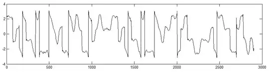
the raw ("real") modulated signal, or the demodulated ("complex" I,Q) baseband signal, or I alone, or Q alone -- but I don't think it will work if you feed phase data from the "Update #2" plot above into the FFT.

It's usually pretty easy for a human to visually pick out the -3dB bandwidth on a graph. Is there a Matlab function for estimating the -3dB bandwidth?

When you have pure white noise coming in -- the SNR is too bad -- the -3dB "bandwidth" clearly has nothing to do with any real baud rate, but depends entirely on the filters used in your demodulator.

autocorrelation

You can find the autocorrelation of a function using the Matlab autocorr() or xcorr() functions.

There are at least 3 ways of converting that autocorrelation to an estimate of the baud rate:

  • With approximately uncorrelated data bits, the autocorrelation at offset time of exactly 1 symbol_time or more are going to be approximately zero, and the normalized autocorrelation at short offset times from 0.0 to 1.0 bit time is approximately linear: 1-(time/symbol_time). Fit a straight line to those short offset times to get a good estimate of the autocorrelation at non-integer offset times, find offset time t_half that gives an estimated autocorrelation of about 1/2 along that fitted line, and your symbol time is about symbol_time ~= 2*t_half.
  • During burst transmissions, some transmitters make every 10th bit a start symbol. Your autocorrelation function, as always, has one peak at 0 offset time; skip past that first peak, and search for the positive time t_positive that gives the next biggest positive peak (with expected amplitude roughly 1/10) in the autocorrelation function, and your symbol time is about symbol_time ~= t_positive/10.
  • Some transmitters use a stop symbol precisely 9 bit-times after every start symbol, and give the stop symbol the negative amplitude of the start symbol. Search for the offset time t_negative that gives the biggest negative peak in the autocorrelation function (with expected amplitude roughly 1/10), and your symbol time is about symbol_time ~= t_negative/9.

autocorrelation approximation

Many other techniques use some quicker-to-calculate approximation of the autocorrelation function -- in particular, there's really no point computing the autocorrelation amplitude at offset times greater than 10 bit_times.

In particular, let's calculate the autocorrelation function at only one time offset H: Delay the signal by some time H, and multiply the delayed signal by the original (non-delayed) signal, and use some perfect or leaky integrator get a long-term average. (If your input signal is already clipped to the +1 -1 range, like most FM and PSK receivers, then that long-term average is already normalized. Otherwise, normalize by the average of the square of the signal, so your long-term average is guaranteed to be in the range of -1 to +1).

Then tweak H to try to get that normalized long-term average to be exactly 1/2 -- make time offset H shorter if the normalized long-term average is less than 1/2; make H longer if the normalized long-term average is more than 1/2.

Then your symbol time is about symbol_time ~= 2*H.

other techniques

The wikibook "Clock and Data Recovery" sounds promising, although it is still a rough draft. Could you update it to tell what approach worked best for you?

I've been told that many receivers use a Costas loop or some other relatively simple carrier recovery technique to detect the baud rate.

The communications handbook mentions a "early-late gate synchronizer". Could you use something like this?

details

Many wireless communication protocols add many "redundant" features to the signal in order to make it easier for the receiver to lock onto and decode the the signal in spite of noise -- start bit, stop bit, trellis modulation, error detection and correction bits, constant prelude and header bits, etc.

Perhaps your signal has one or more of these features that will make your job easier?

davidcary
  • 17,426
  • 11
  • 66
  • 115
  • Thanks. Not sure about `FFT` because the noise would create high frequencies in the spectral domain. The auto-correlation would be the right solution for this problem. There is no *burst transmits* and no **stop-bits**/**stop-symbols**. The first option you suggested in *autocorrelation* section is what is called cyclostationary properties of signal. Based on the cited paper in the question, this method is not robust when the sender uses raised-cosine shape filter with a small roll-off (a<0.3). The paper suggest an improved method. I hope i can find an implementation of that method. – Isaac Feb 18 '11 at 14:19
  • FFT: Yes, noise will create a bunch of spurious peaks at higher and lower frequencies -- but if you are lucky, your SNR ratio is good enough that all those peaks falls below -3dB below the peak level, and you can ignore them. Do the FFT, pick a cutlevel of half of the peak amplitude of all the bins, zero out all the FFT bins with an amplitude below the cutlevel, and count how many (hopefully consecutive) nonzero bins remain. With reasonable amounts of white noise, there's not enough noise to push the high and low frequencies above the cutlevel and so they will still be zeroed out and ignored – davidcary Feb 28 '11 at 18:57
1

If you know your symbol shape is a square pulse, then you know this will be a sync function in the frequency domain. If you take an FFT of the signal and measure the width of the first lobe of the data (or 2x the lobe at baseband), that will be your symbol rate.

An early-late gate symbol synchronizer can easily be implemented, but you'll need to first run the data through a matched filter, which will require at least an estimate of the symbol rate.

gallamine
  • 1,112
  • 3
  • 11
  • 19
0

Maybe we're talking at cross purposes here, but automatic baud rate detection for UARTs is a done deal in the microcontroller area - and it doesn't seem to require advanced algorithms. Of course, your standard 8-N-1 serial connection requires one START bit, so if you can find that and time it you're set (especially considering that there are only certain allowable baud rates - 115200, 38400, etc).

There's C code to do autobaud on a serial line for AVRs here (and also a short explanation of the algorithm): http://mycal.net/?cpath=/Archive/&id=569&action=9

But I think that you are looking for something more general than this?

AngryEE
  • 8,669
  • 20
  • 29
  • 2
    Yes. I am looking for a way to detect symbol rate for a general received signal, not just for standard serial ports. In addition, there is no START or any other kind of flag symbols to help the receiver. – Isaac Feb 17 '11 at 14:43
0

I don't know of any prebuilt method for doing this, it seems rather unique to me, at least with the experience I currently have. But for academic sake I am going to see if I can write out my approach to a problem like this.

In this situation a Symbol rate would show up as a shapes being stretched or shrunk. I would take the shapes and "slide" them across the spectrum looking at the correlation. I would then do this many many times with different "stretching" of the shapes, hopefully there are some standard symbol rates that you can use.

You should then be able to analyze what symbol rates had the best correlation.

There may very well be an easier way to do this, but it is all I can come up with right now.

Kellenjb
  • 17,509
  • 5
  • 51
  • 87
0

The generic problem is called "clock recovery", and many times a phase-locked-loop is used. Every time a data edge occurs, the PLL compares it to the clock edge from the local VCO. If the local clock is early or late, the natural PLL action is to adjust the VCO frequency just a bit. Eventually lock is achieved at a multiple of the data edge rate.

There must be a minimum number of data edges present for the PLL to lock on to them. This is why bit-stuffing and line encodings such as 8B10B are used to enforce a minimum transition density - otherwise the PLL VCO will drift away from the data clock over a long run of the same bit value.

I suspect your RF channel is using some kind of line encoding already, normally DC-biased signals are avoided in RF modulation, and an encoding is employed to eliminate DC bias (a.k.a. long runs).

Joe Koberg
  • 151
  • 3
  • Thanks. But the clock recovery is done in another module which I don't have access to it. `PLL`s is for *carrier clock recovery* while I am seeking for a method for *symbol clock (rate) recovery* – Isaac Feb 18 '11 at 14:06
  • Nothing stopping you from using another PLL on the symbols. If they aren't bilevel, you really need to expand the question with more information about the encoding. You seem to know what's going on - so why make us poke at answers? – Joe Koberg Feb 19 '11 at 06:37
0

Well if symbols are encoded as different levels of voltage after the filter then looking at your waveform I see 4 levels - that means log2(4) symbols or 2 symbols/baud.

(this is assuming we're not seeing a squished phase modulated signal where the extra phase information is lost)

Taniwha
  • 1,636
  • 9
  • 8
  • Please read the question again. I am looking for a implementation for estimating the baud-rate automatically. The figure presented in the question is just an example. – Isaac Mar 22 '11 at 20:08