-1

I would like to build a water sensor power switch. A device which completes the circuit of an outlet adapter when the water sensor has detected water.

I have a very simple idea about this little project. I will modify this plug in mechanical timer(PIMT).

photo of mechanical timer

photo of water sensor

I will disable the timer within the PIMT, and replace the timer with the water sensor to complete the circuit. Do you guys see any flaws on this modification? (sorry can't find the circuit diagram for the PIMT)

Phil Frost
  • 56,804
  • 17
  • 141
  • 262
  • 1
    It's hard to know without more details on the components, but I'd guess the mechanical timer switches the mains directly using mechnical contacts and the water sensor probably isn't rated / safe for use at mains voltages. – PeterJ Mar 18 '14 at 09:10
  • Hi Peter Thank you for you reply. Do you think i should make one by myself instead? like using a relay to connect to the main voltage? – mathwannabe Mar 18 '14 at 09:21
  • 1
    These kind water level float switch (at least the ones I see all over ebay) are rated for 220v mains but for just 0.5A (and highish resistance) so it's not a good idea to be used directly with a load but can drive a relay or other control circuit. Your timer seems to me a mechanic one (the output switch is controlled mechanically rather than electrically) so I'm not sure how you intend to use the sensor signal to activate it. – alexan_e Mar 18 '14 at 09:25
  • Hi Alexan. So i should use an electrical timer which has a relay in it? I am sorry i can't show you guys any pictures of the components yet. – mathwannabe Mar 18 '14 at 09:30
  • You can make one from scratch, but I'm not sure exactly what you want to do. Do you want the device to turn on/off when the water level goes above a specific level or you want some kind of hysteresis to keep the device working for a while once it is activated, even if the water drops below the reference level? – alexan_e Mar 18 '14 at 09:34
  • I just want a simple on and off switch device. When the water rise up to a certain level, the water sensor would trigger the outlet plugin to go on. And that outlet plugin can therefore feed electricity to a water pump (to suck water out of the tank). And When the water lower back to the normal level, the outlet plugin would stop feeding electricity to the water pump. =) – mathwannabe Mar 18 '14 at 09:38
  • Use a relay, or buy a float-switch that's actually rated for switching a load, plenty of pumps come with such float-switches attached already. – John U Mar 18 '14 at 10:15
  • Hi John. Trust me, building a switch device is the last thing i want to do. – mathwannabe Mar 18 '14 at 10:18
  • 1
    @mathwannabe What you want can be done with a relay and any small wall wart psu. The float switch will control the supply of the relay and the motor will run on/off. I'm not sure what to make of your last comment, does it mean that you don't want to make your own switch? If not then maybe you should look at ebay to find a ready one that does what you want. – alexan_e Mar 18 '14 at 11:13
  • 1
    What has the timer got to do with anything? State what you want to achieve (and if it involves a timer functionally then fine) but don't cloud your question with stuff that is irrelevant to your actual desired solution. What's your budget? How much hysteresis can you tolerate in water level differences? – Andy aka Mar 18 '14 at 11:14
  • Hi Alexan. The wall wart part is interesting .I will do some research on it. – mathwannabe Mar 19 '14 at 09:15
  • If you just want a pump that kicks on when water reaches some level, you don't need to buy or assemble anything. It's called a "sump pump", and any hardware or home improvement or plumbing store sells them. – Phil Frost Mar 19 '14 at 11:28

2 Answers2

5

The simplest way, from a do-it-yourself perspective of someone that has to ask for circuit advice here, to detect water is a float switch. These will be available in most hardware stores around where they sell sump pumps. Complete sump pumps come with a float switch, but they are often available by themselves as replacement parts.

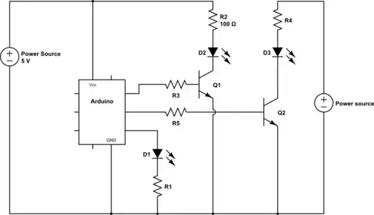
To do this electronically is more complicated. I've had to detect water water before, and a good method is to have two sensors connected to pins of a microcontroller. However, you don't just check for resistance between the two electrodes. There are several issues with two electrodes you have to consider:

  1. Electrolisys. You want to avoid passing any large current and any net DC over time.

  2. Corrosion. This changes the resistance, can cause assymetry, and a battery effect.

  3. Common mode noise.

The way I deal with these issues is to take four separate measurements for each over all reading that is intended to indicate the presence of water. Each electrode is driven strongly high and low. At the same time the other is driven weakly the opposite direction while its voltage is measured. This comes out to a total of 4 measurements that result in no net DC voltage. Do the math and you will see this also cancels out common mode noise, bias caused by the battery effect, and assymetric resistance caused by corrosion.

One set of readings only takes a few 10s or 100s of µs to make. If you only need to know the presence of water every 1 second, for example, then the electrode can be off most of the time. This saves power and reduces corrosion due to electrolosys.

The microcontroller then decides whether water is present or not, and drives a relay accordingly.

Olin Lathrop
  • 310,974
  • 36
  • 428
  • 915
  • Thank you Olin.Yes i know about sump pump.However, sump pump is not a great match for my project. I will follow your guide and do some experiments on it. =) – mathwannabe Mar 19 '14 at 09:04
  • @mathw: Then you should explain what your project really is. It's rather annoying to the volunteers here to write answers only to find parts aren't applicable because you gave incomplete information. You also may get solutions you haven't even considered. Present the real problem, not your imagined solution to a piece of it. – Olin Lathrop Mar 19 '14 at 12:41
  • I am sorry for being so ambiguous about my problem. But i have found a product that solves my problem. http://www.plumbingsupply.com/electronic-utility-pump-switch.html – mathwannabe Mar 20 '14 at 12:18
  • The four electrodes are for a Kelvin connection type setup to avoid the voltage sensing electrodes ever passing a high current to damage them? – Dan Sheppard Mar 31 '22 at 07:26
2

Here's a serious problem: those mechanical timers are based on mechanical switches. You can know this by the loud "thunk" they make when they reach the set time and turn the load on or off. Your water sensor has no way to interface to this mechanical device.

A more subtle problem is that you seem to have very little understanding of electricity, but you are playing with a device that can easily start fires or even injure or kill you or other people. Moreover, you are mixing it with water, which is a very likely way for someone or something to accidentally come in contact with the hazards of your device. Most building codes have special requirements for electrical circuits even near water (bathrooms, kitchens) and even more stringent requirements for devices in water. From your description, you seem to be ignorant of all such regulations, which exist to make such devices safe. I'd advise an abundance of caution.

If you want a safer way to accomplish something like this, I'd suggest investigating generic remote-controllable outlets, such as z-wave outlets sold for home automation. Then your water sensor can control this outlet, via the home automation network, without need to interface with mains voltage. Of course, you might as well buy a z-wave water sensor, and then you don't really need to make anything.

Phil Frost
  • 56,804
  • 17
  • 141
  • 262
  • Thank you for suggesting the z-wave water sensor Phil. Yes, i am ignorant and that is why i am here to learn =) – mathwannabe Mar 19 '14 at 09:04