3

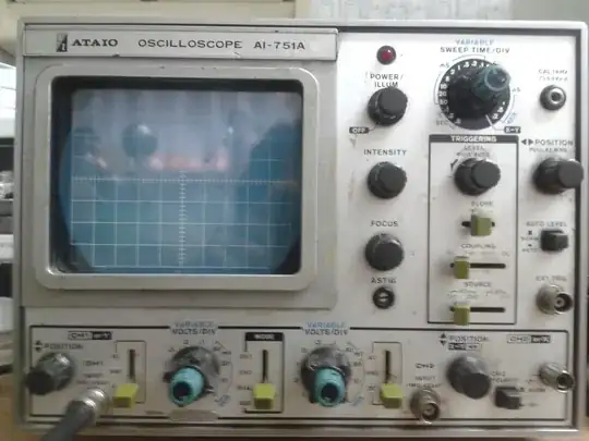
I got an old CRT oscilloscope someone had laying around unused in his garage (an ATAIO AI 751A which seems pretty obscure, not getting any meaningful Google results). Unfortunately the user manual is missing, I couldn't find it online and this is the first CRT oscilloscope I work with, so I'm not sure if I'm operating it properly.

It powers up but there's nothing on the display when the probe is not touching anything, even when it is set to GND. Touching the probe's tip triggers a (very flickery) 50Hz ~10mV peak to peak signal (yes, I'm european) but setting it to GND to center the signal vertically stops showing the signal. At dual display mode both channels are shown when I touch the tip in channel 1 (channel 2 disconnected is shown at ground level), but as soon as I release the finger, both channels are gone too.

Touching a 9V battery gets a single sweep when the tip touches or releases the battery, while I'd expect at least that channel to be shown at a constant value.

Setting a high period for the time division and touching the tip triggers a single sweep, but as soon as it reaches the far right it stops. I can trigger another sweep touching or releasing the tip again.

I pressed a switch labelled "Auto Level" which I think should make the trigger level automatic based on the last samples (which seems plausible since the trigger controls don't do anything when auto is on) but still nothing is shown on the display when touching a 9V battery.

Fiddling with the controls (e.g. pressing the "Auto Level" switch) triggers a single sweep too.

Is the oscilloscope broken or am I doing something wrong? Where should I start troubleshooting?

Images: (don't pay attention to the settings)

Full oscilloscope enter image description here

Triggering controls close-up enter image description here

Nick Alexeev
  • 37,739
  • 17
  • 97
  • 230
DuckTyped
  • 452
  • 4
  • 11

2 Answers2

5

Pull out the trigger level knob. This will put it into "auto" trigger mode, which basically means it will automatically start a new sweep a short interval after the previous one ends. This will give you a continuous trace even with a DC input signal.

On modern scopes that have microprocessors, "auto" now means something completely different, in which the micro searches for a set of vertical and horizontal settings that give a "reasonable" display (YMMV).

The "Auto Level" button does something different: It uses a pair of peak detectors to determine the swing of the signal, and places the trigger level at some intermediate (50%?) value.

Dave Tweed
  • 168,369
  • 17
  • 228
  • 393
  • I almost couldn't believe it would be that easy when I pulled the knob and it actually worked! Thanks. Now I see what "PULL AUTO" meant, I can't believe I didn't realize it before. The rate of triggering is controlled by the sweep time, right? – DuckTyped Mar 17 '14 at 18:54
  • 1
    Generally, yes. Usually, there's a fixed delay between sweeps, so at slow sweep speeds, the sweep time dominates, while at the highest sweep speeds, the delay time dominates and the trace gets dimmer as a result. – Dave Tweed Mar 17 '14 at 19:01
  • 2
    @DuckTyped some scopes have a "hold off" setting which adjusts a delay after the sweep until the trigger is armed again. – Phil Frost Mar 17 '14 at 19:49
  • No fair figuring out the answer with a photo to work from ! ;) – Scott Seidman Mar 17 '14 at 21:46
1

I suspect your scope is fine, and you just need to manually set the trigger mode, channel, and level. Even on today's modern digital scopes, hitting an AUTO button does things you don't want it to do.

Further, pretriggering on these dinosaurs is difficult or non existent, so the trigger point will be at the far left of the screen, and not the center, which you're probably used to.

You'd be better off starting your experience with a sine or square wave than with a DC battery. Is there a little doohickey coming off the front somewhere that provides a square wave output for adjusting your probe? That would be a convenient source to play with.

Scott Seidman
  • 29,274
  • 4
  • 44
  • 109
  • Yes, there is a square wave output for calibration! Completely missed that, very convenient. My trigger settings are set to: "Slope +", "Source CH1", "Coupling DC" and a "LEVEL - PULL AUTO" knob which does what it should with AC as far as I can understand, but nothing when touching the battery. It still seems weird I can't get the flat output even with input set as GND. – DuckTyped Mar 17 '14 at 17:45
  • Often there's a "find trace" button that can help figure out what the scope is seeing. Maybe your trace is just out of range. Start by setting the trace on GND and push "find trace", and setting the trigger to auto. Play with the offset controls and see if you can find your trace. – Scott Seidman Mar 17 '14 at 17:48
  • You want the scope on DC to start. – Scott Seidman Mar 17 '14 at 17:48
  • What are your choices for source? – Scott Seidman Mar 17 '14 at 17:56
  • Yes, the scope is on DC. There is no "find trace" button, but I'm sure it's in range since it shows fine for a single sweep when I fiddle with the controls and I managed to center it setting it to GND and using channel 2 to trigger the display touching the tip with my finger. It even traces an horizontal line at 9V if I touch the battery and trigger with my finger in channel 2... it just seems to refuse drawing unless I do the "channel 2 finger" trick. – DuckTyped Mar 17 '14 at 17:58
  • Right now only tested on a 9V battery (which displays nothing unless I do the trick) and my finger (yes... I know, but it triggers!) I'll get an AC source in a few hours, but it seems weird it's not drawing when I set it to GND unless I do the channel 2 trick, sine it makes it very hard to center the GND level and it's definitely not what I expected (what's the use of the GND switch if it draws nothing?) – DuckTyped Mar 17 '14 at 18:00
  • Are all your "inside" knobs set to their click setting? Gains on these scopes should have infinite settings, with only the far counter-clockwise (usually) "clicked" in to the calibrated setting on the dial. Same for time. This probably isn't your problem, but you should make sure the scope is set correctly before you mess around too much. What happens when you try to trigger off the probe cal signal?? – Scott Seidman Mar 17 '14 at 18:03
  • With "inside" you mean the calibration knobs? These don't click, but they're turned all clockwise (which reads as ~20ms, or 50Hz, when picking mains RF in my finger). The calibration signal works fine and I read 1kHz (as printed below the calibration socket) and the Vpp seems fine too, but again setting it to GND makes the traces disappear. Using the calibration signal as a trigger with the oscilloscope set to DUAL works fine and I can see and adjust the GND level in the second channel just fine. – DuckTyped Mar 17 '14 at 18:20
  • Thanks for the photo. I mean the blue knobs inside of the gray knobs. You should DC couple your trigger. – Scott Seidman Mar 17 '14 at 21:44
  • @DuckTyped I don't see this answered yet, so I'll give it a shot here: each oscilloscope channel usually has options for DC/AC/GND coupling. DC basically shows the voltage difference between the probe tip and the ground clip (which is correctly connected to building ground, [be careful](http://electronics.stackexchange.com/questions/4923/why-does-oscilloscope-cause-short)!) modulo overall bandwidth. AC shows that, but with any DC offset filtered away. GND just shows nothing, intentionally. I assume it's purpose is for sanity check/position adjustment — at least that's all I know to use it for. – natevw May 15 '15 at 17:36