2

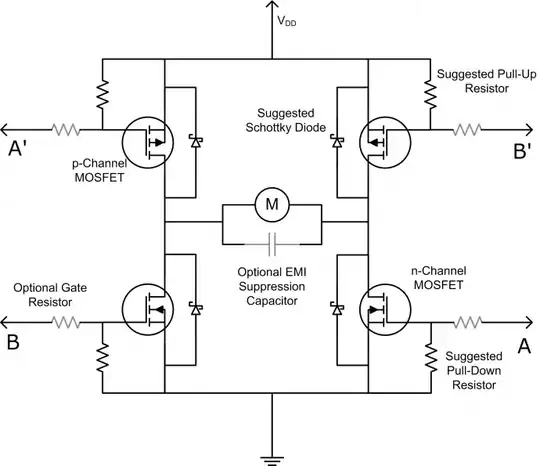
I want to create an H-bridge using MOSFETS (IRL620SPBF). I am trying to run a 6V motor which requires max current of 1.2A . The transistors Q111 and Q112 provide level conversion as the 'signal' comes from a Dev board at 3.3V. The DAC signal comes from the Dev board (0 - 3.3V). For prototyping purposes I created an oscillator from 555 timer to act in place of the DAC signal. The frequency ranges from 0 to 1.7KHz. The circuit works but I noticed a few drawbacks. Firstly, the mosfet Q1 gets really hot. These mosfets are rated at 5.2A, 200V which is well within my range. I do not understand why only Q1 gets hot and not Q4. Doesn't the current going through Q1 also goes through Q4 or is there something wrong with the circuit design or is it to do with the switching of the mosfet? I have provided the h-bridge circuit below:

enter image description here

Any comments and suggestions are welcome

EDITED

New development. Just noticed that when the motor is disconnected from the circuit and the power is connected, mosfet Q3 gets hot. Is this magic?

EDIT 18 March 2014 - Discussion

I took out mosfets Q1 and Q3 and directly connected them to 6V and sending PWM signals to FETS Q2 and Q4. I noticed that the fets get a little warm when driven the motor at full load but they do not get hot at all. When I was using the 4 FET h-bridge I noticed that the top fets would get really hot which was due to improper biasing (the fets weren't switching on fully). The new design is a great improvement. Now I am choosing an N-channel mosfet with much lower Rds(on) compared to the one I am using at the moment which will be STB80NF55L-06T4. Hope that would not consume too much power and dissipate heat. Thank you all

David Norman
  • 1,475
  • 2
  • 20
  • 31
  • Sounds like Q1 isn't fully saturated. – Ignacio Vazquez-Abrams Mar 16 '14 at 19:18
  • 2
    Your high side switches Q1 and Q3 are N-mosfets with the Drain connected to 6v, and you are trying to drive the gates with the same 6v. That is what creates the problem. Please refer to [this reply](http://electronics.stackexchange.com/a/95260/33841) – alexan_e Mar 16 '14 at 19:25
  • I was thinking to replace resistor R104 which is a 1K resistor with a smaller value. I read somewhere that the internal capacitor can sometimes not fully charge because of high gate resistance. Am i right? – David Norman Mar 16 '14 at 19:27
  • 2
    You apply 6v to both the Gate and Drain so the Source becomes 6v (at least tries) when the upper mosfets conducts. That reduces Vgs and makes the device work in a half open state where the resistance and voltage drop (across Drain-Source) is increased and that is the cause it gets heated. No resistor change is going to help. You either need a higher voltage source (e.g. 12v) or an isolated voltage source (a separate isolated source to drive the Gates). Of course you can also use P-mosfets for the high side which would work fine. – alexan_e Mar 16 '14 at 19:37
  • Alexan_e is fully correct. Additionally: what are those relays doing in the source lines? One gate of both sides is always left unconnected??? – Wouter van Ooijen Mar 16 '14 at 19:46
  • N-Mosfets are known to work great for high switching, but P-mosfets are not recommended for this purpose right? Also, 6V is the requirement of the circuit. I was thinking to use an OPAMP to boost the gate voltage but I don't think that's a wise option – David Norman Mar 16 '14 at 19:47
  • @WoutervanOoijen, the relays are used to provided a protection against accidentally switching Q1 and Q2 at the same time or Q3 and Q4 which will cause a short – David Norman Mar 16 '14 at 19:49
  • @WoutervanOoijen, is that why Q3 gets hot when power is ON but motor is disconnected because Q3's gate is left floating? – David Norman Mar 16 '14 at 19:55
  • Could be. But why on earth would you want to leave a MOSFET gate floating? – Wouter van Ooijen Mar 16 '14 at 19:57
  • @WoutervanOoijen, I don't know I wasn't thinking straight, but now these problems arise and I realise what I've done wrong – David Norman Mar 16 '14 at 20:00
  • 1
    Success with modifying the circuit. I suggest you take P FETs for the top positions. OR: if you include a relay for reversing the direction, you need only 1 FET! – Wouter van Ooijen Mar 16 '14 at 20:06
  • @WoutervanOoijen, P FETs on top side would not be good for fast switching, but what if I use P FETS for top side and N FETS for bottom and run PWM from bottom? But I shouldn't have to do all this because the circuit should work with 4 N FETS. What if I use an OPAMP to boost the voltage at Q111 and Q112 circuit? – David Norman Mar 16 '14 at 20:11
  • P-mosfets are not as bad as you think, but if you have a voltage higher than 6v available then you can easily solve the problem by applying that voltage to the gates. If you don't then an OPAMP can't do anything, best case it can output a voltage as high as its power supply (rail to rail OPAMPS) – alexan_e Mar 16 '14 at 21:20
  • @alexan_e, Brian Onn advised that I use Voltage double using 555 timer. You reckon if I can get 9V from that it would be sufficient to saturate the mosfet? The max Vgs for this FET is 10V – David Norman Mar 16 '14 at 21:35
  • You can use 555 to generate a higher voltage but I think it's pointless and complicates things with no reason. I just took a look at the datasheet of your mosfet. It has an Rds-on rating of 0.8 Ohm at Vgs=10v (probably about 1 Ohm at Vgs=6v). You can find P-mosfets with an Rds-on several magnitudes lower than that, so I don't see why you worry and you insist on using all N-mofets. If you were using some 0.005 Ohm N-mosfets then maybe it would be worth avoiding P-mosfets (although they have evolved) but at the current situation I don't see any reason to not use them. – alexan_e Mar 16 '14 at 21:40
  • @alexan_e, I don't have to use N Fets. I am now exploring other options. Looking into P Fets now – David Norman Mar 16 '14 at 21:44
  • @alexan_e, If I use P Fets, the gate voltage still has to be higher than the source voltage right? – David Norman Mar 16 '14 at 21:50
  • @Dave for a P FET everything inverts, so the gate is driven by a LOWER voltage (which is what you have when your P FET hangs on the positive rail). BUT did you read my suggestion? When you use a relay for inverting the motor direction you need only ONE MOSFET! – Wouter van Ooijen Mar 16 '14 at 22:11
  • @WoutervanOoijen, your suggestion was sound. I spoke to my supervisor that my mosfet is getting hot and he said 'GREAT' put that in your report. So I asked him since I am using Relays I don't have to use any mosfet on the high side. He said explore all options and get back to me. So that is what I'm doing. Exploring – David Norman Mar 16 '14 at 22:15
  • @DavidNorman For a High side P-mosfet the Source will be tied to +6v. When you apply 6v to the Gate than Vgs=0v and mosfet is off, when you apply 0v to the Gate (gnd) then Vgs=-6v and the mosfet turns fully on. – alexan_e Mar 16 '14 at 22:22
  • @WoutervanOoijen, you reckon if I use two FETS with source connected to ground, the FETS should not heat up and should saturate since their source pin connects to GND? – David Norman Mar 16 '14 at 22:25
  • @alexan_e, I figured I am now trying to minimise the amount of components I have used. I was thinking of directly connecting the motor to 6V supply and use an N-channel FET at the bottom and trigger that through PWM? you think that the FET will get hot? – David Norman Mar 16 '14 at 22:31
  • I don't think so, your switching rate is not too high so as long as your driver can charge the gate at an adequate rate you will not have problems. Your mosfet has a total gate charge of 43nC max and your 1.7KHz rate period is 0.59ms. If we assume 1% min duty then a pulse will have a (min) duration of 59us. If your driver can provide about 10mA then the mosfet will take about 4.3us to switch which would be fine. – alexan_e Mar 16 '14 at 22:43
  • @DavidNorman several times in the comments you have asked "do you think the mosfet will get hot".. since you appear to be a student, then I think it is a good exercise for you to figure out yourself if you think that the MOSFET will get hot or not... remember that heating is caused by power dissipated in the device, and power = VxA = Voltage across the device times the current through the device. So try to look at the NFETs and PFETs in their ON configurations, in all possible scenarios ie. when you remove bias power, or remove the motor, etc. Try to determine the power dissipated in the FETS – Brian Onn Mar 17 '14 at 01:38
  • In normal operation, the FETS are either fully on or fully off, and any power dissipation more than a few watts will feel too hot to touch. The power dissipation comes from the channel resistance Rds(on) being too high when not fully enhanced because the Vgs is too low (using PFETs on the high rail won't have this problem, although in general PFETs have higher Rds(on) and this needs to be considered. With your lower current motors then PFETs are likely to be ok in this application, as @alexan_e has said many times) – Brian Onn Mar 17 '14 at 01:49
  • @BrianOnn, I calculated the power dissipation before using these mosfets. The mosfet is rated at 5.2A, 200V whereas in my design, when the motor is fully on the mosfet conducts about 1.5A (maximum) and runs at 6V. That is within the range of the mosfet. It still gets hot which I think is because I am not providing enough voltage to the gate. So tomorrow I will try a few other things – David Norman Mar 17 '14 at 05:16

1 Answers1

5

To turn on any of the MOSFETs properly in your circuit, the gate voltage has to be significantly higher than the source voltage. For the lower position devices Q2 and Q4, the sources are grounded to 0V therefore they can easily turn on into "saturation" by applying a gate voltage of a few volts above ground.

For the devices connected to the top rail, if you want the on-resistance between drain and source to be really low you have to obey the same rule - the drive voltage to the gate has to be several volts above the source. Now for low volt drop you want the source to be switched virtually to 6V - where in the circuit can the gate receive a voltage of maybe 9 or 10 volts?

There isn't one so please consider two options: -

  • Using P channel MOSFETs at the top rail, source to 6V. P MOS is slower than N MOS but in your application it won't make a difference (1.7kHz).
  • Using a drive circuit derived from a supply voltage that is at least 9V and quite possibly higher to get the best saturation from the MOSFETs.

Now the relays. What are you hoping to achieve here? The MOSFET whose gate is disconnected will float to some almost random voltage level and possibly turn on unexpectedly or just get hot. Get rid of the relays unless you have some cunning plan for their use which eludes me.

This is a standard H bridge using P and N MOSFETs: -

enter image description here

Please ask if you need recommendations for devices.

Andy aka
  • 434,556
  • 28
  • 351
  • 777
  • Thanks for your answer, it looks like it will solve these problems. With the Relays I was hoping to avoid a short circuit situation by turning ON both switches on either side. Also I do not have any other supply on my board apart from 6V. Can I use an OPAMP to perhaps boost the voltage to a value above 6V? – David Norman Mar 16 '14 at 21:00
  • Only if you supply the op amp with more than 6V. – Ignacio Vazquez-Abrams Mar 16 '14 at 21:01
  • I'm screwed. I have no other supply apart from 6V – David Norman Mar 16 '14 at 21:02
  • @IgnacioVazquez-Abrams, I have a 6V supply from which I regulate 3.3V to power up 555 oscillation circuit – David Norman Mar 16 '14 at 21:10
  • 1
    @DavidNorman you're not screwed. You can use a 555 timer to make a charge pump (switched capacitor) voltage doubler circuit. This will give you approximately 12V from your 6V at about 20-50mA. And once you have a 12V supply you can go back to N mosfets again :) http://imgur.com/RkvcZHQ – Brian Onn Mar 16 '14 at 21:12
  • @BrianOnn, Thanks for your suggestion. I am looking into it. Max Vgs for this mosfet is 10V so I reckon 9V should be fine to drive the mosfet. Would 9V be enough to saturate the fet? – David Norman Mar 16 '14 at 21:32
  • @DavidNorman 10V sounds low. What MOSFET is it and how much current does your load need at full whack? Using N mos at the top is more complex - given that you are only switching at up to 1.7kHz and that your application is probably less than 6A, P FETs will work fine by a mile. – Andy aka Mar 16 '14 at 21:33
  • @Andyaka, I am using IRL620SPBF N MOSFET. The max current that the motor would require is 1.5A at full speed (outer limit) – David Norman Mar 16 '14 at 21:37
  • @Andyaka The mosfet model as well as the load current are given in the first two lines of the question, I guess you missed them. – alexan_e Mar 16 '14 at 21:44
  • @Andyaka, If I connect one terminal of the motor to 6V and the other to the drain of the N-channel MOSFET you reckon the FET will get hot? As you mentioned, the FET connected at the bottom will saturated as its source is connected to GND???? – David Norman Mar 17 '14 at 01:00
  • 1
    @DavidNorman That should be OK - it's the fets at the top you aren't driving correctly. Having said that the IRL620S is a poor choice for this application. You should consider using a much lower Rds(on) device. You don't need 200V rating either, provided you use a fly-back diode on single ended drives (not top FET). Rds(on) is 0.8 ohms and at 1.5A through the device power dissipated is 1.8 watts- try and find a device that is more like 0.05 ohms and sacrifice the 200V rating. – Andy aka Mar 17 '14 at 08:26