6

I built an SMPS (see here for details), and so far it's been working good. But I noticed a strange oscillation (or ringing?) at the output.

Here's what it looks like, with a 4 amps load:

enter image description here

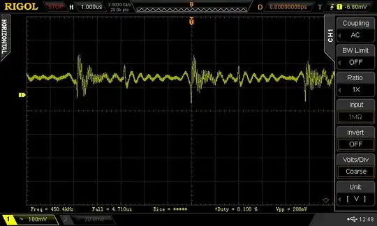
Now, you'll see a HF oscillation when the switch turns on (right at the center of the image, for example). I measured this at 15MHz and figured the MOSFET needed a snubber. I added one (10nF + 10R in series, across D and S), and the 15MHz ringing went away completely.

But I still have that "larger" ringing that can be seen in the picture, around 3.5-4MHz.

What is this ringing?

Is it harmful?

If it is: How can I fix it?

EDIT: Here are some measurements (transient response, voltage across MOSFET and diode, etc). http://imgur.com/a/Qs351

hjf
  • 1,069
  • 2
  • 14
  • 24

2 Answers2

7

The inductor has got parasitic capacitance that forms a resonant circuit at a high frequency. The action of switching current into it and turning it off ALWAYS causes this to happen on pretty much ALL power supplies of this type. The leakage capacitance of the series MOSFET also interacts with the inductance to modify this too.

The inductor is 27uH and maybe the MOSFET has 200pF D-S capacitance - this would cause a resonant frequency of: -

f = \$\dfrac{1}{2\pi\sqrt{LC}}\$ = 2.16 MHz

OK I'm just guessing at what \$C_{DS}\$ is but it's definitely in the same ballpark as you figures. You don't need to add a snubber - doing so will reduce the efficiency of your circuit and what are you trying to "protect" against?

Andy aka
  • 434,556
  • 28
  • 351
  • 777
  • I'm just curious about why that oscillation happens. And i should have also ask if it's harmful or not. The MOSFET is an IRF9540 (http://www.irf.com/product-info/datasheets/data/irf9540n.pdf). How do I determine Cds? Is that Ciss+Coss ? – hjf Mar 12 '14 at 12:58
  • Coss is Cds and is 400pF. It's not harmful in fact it slows down the reverse voltage spike when the transistor turns off. It happens whenever you apply voltage or current transients to an inductor/capacitor - it's basic theory. – Andy aka Mar 12 '14 at 13:27
2

I wouldn't be concerned unless you see true signs of instability, like severe duty cycle jitter or a pronounced low-frequency oscillatory tendency in your output.

Well-designed switching regulators typically target 1% of the DC output level as an acceptable peak-to-peak PARD (periodic and random disturbance, a.k.a 'noise') limit, measured with attention paid to CM pickup (direct coax or a short-ground probe) and some small load capacitance (often a combination of low ESR electrolytic and ceramic).

I suspect the HF noise you see on switch turn-on (and turn-off) may be influenced by how you're measuring it. The lower frequency portion is well below 1 division (or 100mV) on your scope, so it's not a cause for concern in my estimation.

Adam Lawrence
  • 32,921
  • 3
  • 58
  • 110