41

Just now I realized that the I2C data and clock lines (SDA and SCL) must have pullup resistors.

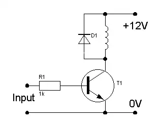
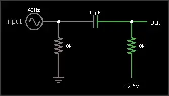
Well, I've built a couple of clocks using the DS1307 RTC (see datasheet) according to the schematic below. Notice that I have omitted both pullup resistors.

Schematic of my clock without pullup resistors on I2C lines

Both clocks work fine, one of them is working for more than 3 months now. How is that possible? In any case, I wanted to know:

  1. What happens when the I2C pullups are omitted?

  2. Is the lack of pullups likely to damage any of those two ICs in my board?

I'm after answers that address my specific case of connecting ATmega328P to a DS1307 RTC like in the schematics I provided, but if the question doesn't get too broad, it would be helpful to know what happens when the pullups are omitted in general, i.e., in other scenarios of I2C operation.

PS. I did search the Net to find the answer, but could just find articles about dimensioning the pullups.

Update: I'm using Arduino IDE 1.03 and my firmware handles the RTC using the DS1307RTC Arduino lib (through its functions RTC.read() and RTC.write()). That lib in turn uses Wire.h to talk to the RTC.

Update 2: Below are a series of scope shots I took to help explain how the I2C is working without the external pullups.

Scope shot 1 Scope shot 2

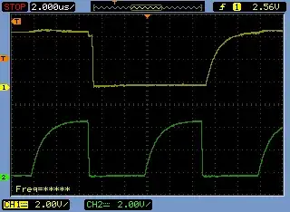
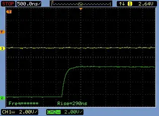
Update 3 (after I2C pullups added): Below is another series of scope shots I took after adding proper (4K7) pullup resistors to the I2C lines (on the same board). Rise times dropped from about 5 µs to 290 ns. I2C is much happier now.

Scope shot 3 Scope shot 4

Ricardo
  • 6,134
  • 19
  • 52
  • 85

7 Answers7

39

1) What happens when the I2C pullups are omitted?

There will be no communication on the I2C bus. At all. The MCU will not be able to generate the I2C start condition. The MCU will not be able to transmit the I2C address.

Wondering why it worked for 3 months? Read on.

2) The lack of pullups is likely to damage any of those two ICs in my board?

Probably not. In this particular case (MCU, RTC, nothing else), definitely not.

3) Why was the MCU able to communicate with the I2C slave device in the first place? I2C requires pull-up resistors. But they weren't included in the schematic.

Probably, you have internal pull-ups enabled on the ATmega. From what I've read1, ATmega have 20kΩ internal pull-ups, which can be enabled or disabled from the firmware. 20kΩ is way too weak for the I2C pull-up. But if the bus has a low capacitance (physically small) and communication is slow enough, then 20kΩ can still make the bus work. However, this is not a good reliable design, compared to using discrete pull-up resistors.

1Not an ATmega guy myself.

update: In response I2C waveforms, which were added to the O.P.
The waveforms in the O.P. have a very long rise time constant. Here's what I2C waveforms usually look like

enter image description here

PIC18F4550, Vcc=+5V, 2.2kΩ pull ups. Waveform shows SCL. The rise time on SDA is about the same. The physical size of the bus is moderate: 2 slave devices, PCB length ≈100mm.

ford
  • 352
  • 1
  • 9
Nick Alexeev
  • 37,739
  • 17
  • 97
  • 230
  • Thanks for your answer! Yes, the ATmega has pullups that must be enabled in my case. I'll double check the code and the libs I'm using and also put the board through the scope. I hope that will clear things a bit. – Ricardo Mar 12 '14 at 04:09
  • 2
    You may want to double check with with the datasheet of your slave device first. If I remember right, the pullups on the ATMega's can be anywhere from 30k-60k (it depends on Vcc, temperature, and a number of other factors; you can't really depend on them for a reliable resistance). You want to make sure you're sending enough current to the slave to ensure a proper logic 1. If the resistance is too large, your slave device won't get enough current and you'll be in the same spot you're in now. – audiFanatic Mar 12 '14 at 04:47
  • I recently used I2C for an accelerometer (Invensense MPU-6050) and the recommended pull-ups were less than 30k if I remember right. Fortunately, the breakout board I used had them built in, so I didn't have to worry about it. For $7, you can't beat this little guy; Sparkfun wants $40 for the same chip and the board has nothing else on it. This one has pull-ups and 3.3V regulators so I can connect it with 5V devices. http://www.amazon.com/Kootek%C2%AE-Arduino-MPU-6050-gyroscope-accelerometer/dp/B008BOPN40/ref=cm_cr_pr_product_top – audiFanatic Mar 12 '14 at 04:50
  • 5
    @audiFanatic +1. BTW, IMO, including pull-up resistors into the breakout boards and installing them by default is an error. Imagine what happens if somebody has multiple breakout boards on one I2C bus. Each pull-up is usually 2.2kΩ or so. The pull-up resistors on all of the break out boards appear in parallel. Combined pull-up becomes too stiff for I2C. \[More about this potential problem [here](http://makersconfidential.blogspot.com/2015/10/i2c-pull-up-resistors-on-modules-and-breakout-boards.html) and [here](http://electronics.stackexchange.com/q/68096/7036).] – Nick Alexeev Mar 12 '14 at 05:03
  • True, I never thought of it that way. I didn't really bother with it because I only have one thing on the bus. Good to know for the future though – audiFanatic Mar 12 '14 at 05:28
  • Just so you know I've added a few scope shots to help clarify what's going on with my setup. – Ricardo Mar 12 '14 at 22:29
  • 2
    @Ricardo That's not a happy I2C bus on your scope shots [first set of scope shots in the O.P.]. I've added a scope shot to my answer too. – Nick Alexeev Mar 12 '14 at 22:59
  • 3
    This article has some waveforms of good and bad i2c signals: http://dsscircuits.com/index.php/articles/47-effects-of-varying-i2c-pull-up-resistors – ford Mar 13 '14 at 04:18
  • @nick not an error. A feature. Its easier to disable the extra pull-ups then it is to add them, to a module. – Passerby Mar 13 '14 at 04:19
  • @Passerby Not a feature. A missfeature. A flaw. Not everyone is aware that too many pull-ups in parallel will cause a problem. (For example, audiFanatic didn't know. This issue of pull-ups on multiple breakout boards has come up on EE.SE before.) The only honest way to make it a feature is to leave pads for the pull-ups on the breakout board unpopulated, include pull-up resistors separately in the kit, add a paragraph to the manual and schematic for the board. – Nick Alexeev Mar 13 '14 at 04:37
  • @Passerby Why are Sparkfun and such doing it the way they are doing it? They want easy out-of-the-box experience. A lot of their customers use just one breakout board, so they don't run into the issue of parallel pull-ups on multiple breakout boards. But when they do run into it, they may be completely baffled: "*each little board works ok separately, but they don't work together. wtf.*" A lot of breakout board users are new to the I2C. The purpose of pull-up resistors is news to them. They haven't read the I2C spec yet. No offense. – Nick Alexeev Mar 13 '14 at 04:37
  • @ford The link discussing good and bad I2C signals is great. It also addresses how to select good pull-up resistor values according to our own particular design (number of devices attached and their capacitances). Thanks!! – Ricardo Mar 13 '14 at 11:31
  • @audiFanatic: Three factors prevent use with very weak pull-ups: (1) If a device leaks input current to ground, an overly weak pullup might not be able to pull a signal high at all; (2) Inputs with weaker pull-ups will be more susceptible to noise than those with stronger ones; (3) Weaker pull-ups won't pull up inputs as fast as stronger ones. Operating an I2C bus at 400kbps will require fairly strong pull-ups; operating one at 1kbps won't. Even a 100K pull-up would be workable in many cases if one were operating slowly enough. – supercat May 07 '15 at 17:16
22

The library you use, and the libraries it depends on (Wire), enable the internal pull-ups of the ATMega. These are weak pull-ups, and in normal use, supplement any external pull-ups (two resistors in parallel). Due to the relatively high resistance of 20k to 70k, they do not cause much if any issues with external ones in use.

What happens when the I2C pullups are omitted?

Now without external resistors, the weak internal pull-ups are the only thing driving the line high. Depending on your board layout, the speed of your i2c line, how often you access it, external interference, etc, they might work, they might not. You lucked out. You do have pull-ups, just not ones you expected.

The lack of pullups is likely to damage any of those two ICs in my board?

Even without the internal pull-ups, a lack of any pull-ups will not damage either IC. The internal build of i2c device SCl and SDA lines are like NPN transistors. They are Open Collectors, essentially current controlled/switched diodes.

The last thing to note though, having the internal pull-ups on, when your ATMega is at 5v, and the i2c device is a 3.3v only device, can cause issues. Or if you have the internal pull-ups on, and external resistors connected to a 3.3v or other voltage, can also cause issues. Essentially, it's an intentionally ignored bug in the Wire library.

Passerby
  • 72,580
  • 7
  • 90
  • 202
  • 4
    +1 - `You do have pull-ups, just not ones you expected.` - I guess you nailed it. Thanks! – Ricardo Mar 12 '14 at 04:49
  • Just so you know I've added a few scope shots to help clarify what's going on with my setup. – Ricardo Mar 12 '14 at 22:30
  • 2
    @Ricardo yep, seeing those, at 33khz. A third of the lowest i2c spec'ed speed, and the signal is still very bad. At 100khz or 400khz, you wouldn't have working communication. Great thing though, is many i2c devices work at a fraction of the max speeds. Just remember, the internal pullups can be up to 70k ohm, a typical i2c resistor is 4.7k – Passerby Mar 13 '14 at 04:16
9

Generally you will need to have the pullup resistors for an I2C interface circuit. If the interface is truly a full spec I2C on both ends of the wires then the signal lines without the resistors will never be able to go to the high level. They may remain low or go to some intermediate level determined by the leakage current in the parts at each end. The reason for this is because true I2C is an open drain bus.

Some devices may actually have on-chip pullup resistors in the 20K to 100K ohm range just to hold the interface pins at a high inactive level when the I2C interface on the part is not in use. For simple and short interfaces these pullup resistors may be just enough to provide the current needed to pull the lines high while clocks and/or data is being signaled.

It is hard to tell from your schematic but in some instances I2C interfaces are implemented using general purpose I/O port pins and then bit banged in software. Sometimes the implementer may not operate the I/O pins in this configuration using an open drain methodology and this may play a factor on why an interface without pullup resistors may seem to work.

At the end of the day you probably owe it to yourself to check out the signalling on one of your earlier clocks using an oscilloscope to see if the 1's and 0's on the interface are working within spec voltage levels. Then you will know for sure whether you were just incredibly lucky with that implementation or if one of the factors that I mentioned above is at play.

Michael Karas
  • 56,889
  • 3
  • 70
  • 138
5

What happens when the I2C pullups are ommited?

Most likely, the I2C bus will simply not work.

The lack of pullups is likely to damage any of those two ICs in my board?

Most likely not.

The Photon
  • 126,425
  • 3
  • 159
  • 304
4

Your I2C lines will not work at all. If I'm not mistaken, I2C just asserts low signals, but does not return them to back to a high state, which is why you need those resistors.

Any lack of pull-ups should not damage any IC.

Funkyguy
  • 3,558
  • 1
  • 21
  • 45
1

I2C is a TTL-logic protocol; so your data and clock lines are open-drain. In other words, the I2C hardware can only drive these lines low; they are left floating when not a zero. That's where the pull-up resistors come in. This is a simplified diagram, but work with me for a second.

schematic

simulate this circuit – Schematic created using CircuitLab


As you can see; the pull-up resistor is needed to ensure a logic 1 is seen at the output when the TTL logic is not driving the output low. TTL logic cannot drive the lines high as I already mentioned. If this were not present, the output would be left floating and it's unpredictable what you may see at the output (for all you know, your microwave or the intestinal dysfunctions of your co-workers caused by a certain sugar-free gummy bear could cause the value to fluctuate).

Now, if you were to implement I2C in software with a microcontroller, this would likely not be too much of an issue as it will most likely be using CMOS logic, which can drive outputs both high or low.

audiFanatic
  • 419
  • 1
  • 3
  • 14
  • 1
    Glad it helped. – audiFanatic Mar 12 '14 at 04:35
  • 2
    Whether the devices use TTL or CMOS logic doesn' matter - normal TTL and normal CMOS outputs will pull signal both up and down. The I2C signals are either open-collector TTL, or (more likely) open-drain CMOS - in both cases, the transistor that would pull the signal high is missing from the output stage of the source, so pull-up resistors are required to pull the signals high. It is possible that the microcontroller has internal pull-ups on those pint. – Peter Bennett Mar 12 '14 at 06:29
  • 3
    -1 As Peter Bennett said, a lot of this answer is just wrong. Calling TTL signals "open-drain" is the giveaway. – Joe Hass Mar 12 '14 at 10:54
  • Note that there are advantages to doing I2C with TTL, namely that you often don't need level translators to handle components with different supply voltages attached to the same bus. Simply setting the pullup voltage to the highest accepting input voltage of the lowest voltage chip is many times sufficient with TTL *input* stages. On CMOS, that wouldn't work. – Ben Voigt Mar 12 '14 at 15:26
  • @BenVoigt: No - calling the "requires a pull-up resistor" configuration "TTL" is wrong, as this arrangement can be made with either CMOS or TTL, and the DS1307 is a CMOS part. The Maxim datasheet clearly states that the outputs are open drain,and the block diagram shows a FET for one output. – Peter Bennett Mar 12 '14 at 16:04
  • @Peter I completely agree. My comments regard what TTL really is, not the confused version in this answer. You said that TTL vs CMOS doesn't matter, but although input threshold is only tangentially related to weak pullups, it does end up mattering in singe circuits. – Ben Voigt Mar 12 '14 at 16:13
0

When I bit bang I2C with a micro as the master which supplies the clock then I have been able to drive the SCL without pullup.

However, SDA does need to be OC with pullup so the slave device can pull down and respond properly.

Regards

Wayne
  • 1