34

inverting

The gain here is A = -Rf/Rin. However, lets say I want a gain of 10 V/V. Which resistor value would you choose and why?

I know that you could have infinite number of combinations for these resistors but why would some one use specific value. i.e Rf = 100Mohm, Rin = 10Mohm gives a gain of 10V/V but also Rf = 10 ohm and Rin = 1 ohm gives the gain of 10V/V. What difference would it make to the design?

My thoughts say that higher value resistors are not precise so it wouldn't give you precise gain and using lower value resistors sink higher current from the source (Vin). Are there any other reasons? Also, let me know If I am right or wrong as well.

hpekristiansen
  • 295
  • 4
  • 17
dr3patel
  • 1,620
  • 3
  • 22
  • 31

5 Answers5

33

There are downfalls with choosing very large resistors and very small resistors. These usually deal with the non-ideal behavior of components (namely Op-Amps), or other design requirements such as power and heat.

Small resistors means that you need a much higher current to provide the appropriate voltage drops for the Op-amp to work. Most op amps are able to provide 10's of mA's (see Op-amp datasheet for exact details). Even if the op-amp can provide many amps, there will be a lot of heat generated in the resistors, which may be problematic.

On the other hand large resistors run into two problems dealing with non-ideal behavior of the Op-Amp input terminals. Namely, the assumption is made that an ideal op-amp has infinite input impedance. Physics doesn't like infinities, and in reality there is some finite current flowing into the input terminals. It could be kind of large (few micro amps), or small (few picoamps), but it's not 0. This is called the Op-amps input bias current.

The problem is compounded because there are two input terminals, and there's nothing forcing these to have exactly the same input bias current. The difference is known as input offset current, and this is typically quite small compared to the input bias current. However, it will become problematic with very large resistance in a more annoying way than input bias currents (explained below).

Here's a circuit re-drawn to include these two effects. The op-amp here is assumed to be "ideal" (there are other non-ideal behaviors I'm ignoring here), and these non-ideal behaviors have been modeled with ideal sources.

schematic

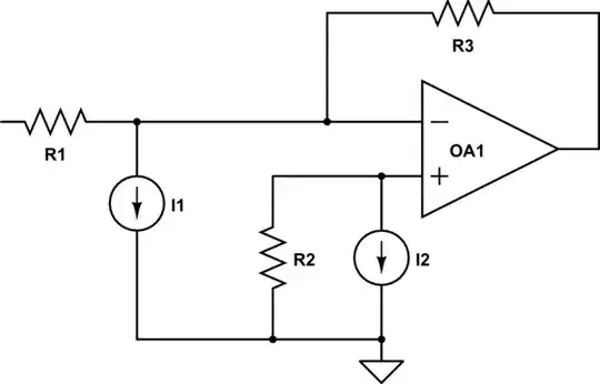
simulate this circuit – Schematic created using CircuitLab

Notice that there is an additional resistor R2. In your case, R2 is very small (approaching zero), so a small resistance times a small bias current I2 is a very small voltage across R2.

However, notice that if R1 and R3 are very large, the current flowing into the inverting input is very small, on the same order as (or worse, smaller than) I1. This will throw off the gain your circuit will provide (I'll leave the mathematical derivation as an exercise to the reader :D)

All's not lost just because there's a large bias current though! Look what happens if you make R2 equal to R1||R3 (parallel combination): if I1 and I2 are very close to each other (low input offset current), you can negate out the effect of input bias current! However, this doesn't solve the issue with input offset current, and there are even more issues with how to handle drift.

There's not really a good way to counteract input offset current. You could measure individual parts, but parts drift with time. You're probably better off using a better part to begin with, and/or smaller resistors.

In summary: pick values in the middle-ish range. What this means is somewhat vague, you'll need to actually start picking parts, looking at datasheets, and deciding what is "good enough" for you. 10's of kohms might be a good starting place, but this is by no means universal. And there probably won't be 1 ideal value to pick usually. More than likely there will be a range of values which will all provide acceptable results. Then you'll have to decide which values to use based off of other parameters (for example, if you're using another value already, that might be a good choice so you can order in bulk and make it cheaper).

helloworld922
  • 16,600
  • 10
  • 54
  • 87
  • 1
    By the way, [more on compensation with R2 = R1 || R3 can be found here.](http://electronics.stackexchange.com/a/45723/7036) – Nick Alexeev Mar 11 '14 at 20:35
  • Does input bias current not reduce with bigger external resistor at the input terminals? – quantum231 Jul 28 '16 at 15:44
  • It might, but it is almost certainly unspecified by how much, non-linear, temperature/temporal drift dependent, and still does not solve the input offset current problem unless you balance both sides. – helloworld922 Jul 28 '16 at 17:10
8

In your specific op-amp circuit, the voltage on junction of Rf and Rin is the same as the voltage on the non-inverting input. This has to be so - it's called a virtual earth. Given that fact, this means that your signal (Vin) sees an input impedance of exactly Rin. It also means that your output (without connecting to anything else) has to drive an output load that is Rf.

These two facts usually dictate that Rf and Rin are not very small i.e. they are 50 ohms or upwards.

The op-amp has other things about it that means you need to avoid the high end resistor values. These are: -

  • Parasitic capacitance from output to inverting input (in effect in parallel with Rf). If Rf is too big the frequency response of the circuit is limited at the high end of the spectrum.
  • Input capacitance can cause some instabilities if Rin is too large
  • Resistor noise with temperature - this is a well-known phenomena and means, for low noise circuit requirements, Rf and Rin should not be too large.
  • Leakage currents in and out of the inputs cause DC errors if the resistors are too big.

I think that's enough for now!

Andy aka
  • 434,556
  • 28
  • 351
  • 777
  • 1
    When you mean the "circuit is limited at the high end of the spectrum", is it same as saying that your bandwidth is dropped! because with bigger Rf your 1/Rf*Cpara has shifted to left! correct me if I misunderstood your answer. – dr3patel Mar 11 '14 at 21:52
  • That's about correct. – Andy aka Mar 11 '14 at 22:23
7

First, your diagram is an inverting amplifier, not a non-inverting as in the heading for your question.

There are some common resistors that make good ratios for gain and better yet, common precision resistors with low temperature coefficient and nice resistance ratios. I like to use the precision parts if at all possible. (Same is true for caps in op-amps like for integrators - polystyrene precision and temperature stable). Like 10K/1K or 33K/3.3K. Beyond 100K/10K the Resistance gets high enough that the small capacitance in the circuit starts to turn your circuit into an integrator or differentiator (or low pass filter).

Very low Rin values load the input and high Rf values increase output impedance. These problems are easily overcome. Most op-amp packages have more than one OA. Use one as a voltage follower and as the input to your OA that has gain. Your total circuit presents a very high input impedance and your OA with gain sees a very low impedance on its input and you can use low values for Rin. You can also use an OA follower on the output to have high drive current and low impedance output. You can even easily configure the output to match impedance of the next circuit or a coaxial cable, etc. I like to use high precision low tempco resistors or low tempco pots (or digital pots) for Rf and trim for gain.

I have used 1M/1K for a gain of 1000 (2 op-amps in a row gives gain of 1 million) with low-pass for seismology, but this is a few Hz bandwidth and works even with the lowly uA741. LM308 requires much less trim. Good modern OA's are great by comparison. If you get into the 10M to 100M area for Rf, your bandwidth will drop off and noise will go up.

C. Towne Springer
  • 2,141
  • 11
  • 14
  • Just looking to confirm this part "(2 in a row gives 1 million)". I assume you mean running 2 op-amps in series (i.e. output of first is input to second), each providing 1000x gain, for a total gain of 1M ? Thanks for the resistor value guidances, very helpful. – Assad Ebrahim Dec 14 '21 at 07:53
  • Assad Ebrahim. Correct. Two in a series. (In fact gain of a million was common in seismology. I suspect you can use less gain today with 22 or 24 bit ADC's.) – C. Towne Springer Dec 15 '21 at 17:04
5
  • One of the important differences it the input impedance that V(IN) sees, which equals R(IN).
  • Another important difference is that with high impedance resistors, you easier pick up noise and the OPAMP's input bias current will have a larger effect on output voltage offset.
  • Also remember that the output must be able to drive the R(F) resistor.
jippie
  • 33,033
  • 16
  • 93
  • 160
4

The claim that "higher value resistors are not precise so it wouldn't give you precise gain" is usually not quite true in itself (but is true by proxy for other reasons, as I will discuss below).

Typically, in a well-designed circuit, the gain will depend on ratios of resistances, and not on individual values. A resistor with a nominal resistance R and a tolerance x can take values between: $$ R_\text{nominal}(1 - x) \leq R_{\text{actual}} \leq R_\text{nominal}(1 + x) $$ Now if we have two resistors which appear as a ratio of each other, the minimum and maximum values of this ratio are given by: $$ \frac{R_{1,\text{nominal}}(1-x)}{R_{2,\text{nominal}}(1+x)} \leq \left(\frac{R_1}{R_2}\right)_\text{actual} \leq \frac{R_{1,\text{nominal}}(1+x)}{R_{2,\text{nominal}}(1-x)} $$

Note, firstly, that the tolerance on the ratio is higher than the tolerance on the individual resistors. This is good to keep in mind if you want a precise gain. However, the gain tolerance does not increase with the nominal resistance values, as long as the ratio is constant.


However, very large resistors do reduce precision because of other reasons. Two that have already been mentioned in other answers are (i) the effect of bias and offset currents; (ii) Johnson noise.

Another reason which hasn't been mentioned is that very large resistors start to be become comparable to the resistance of the environment (e.g. the PCB), especially in the presence of humidity and/or salinity. This does make them imprecise, because they are now seen by the circuit in parallel with whatever is surrounding them.

The bottom line is, try to avoid resistances larger than 1MOhm if possible, and really try to avoid anything over 10MOhm. On the other end of the spectrum, around 1k is usually the lower limit.

MGA
  • 273
  • 3
  • 10