What is the function of the resistor R13 in this circuit?
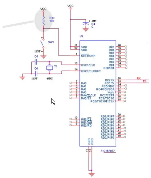
What is the function of the resistor R13 in this circuit?
This is a pull up resistor. When the switch is open, the resistor sets the MCLR pin at VCC.
Without the resistor the pin would be left floating. The MCLR input is a logic input. Which can be 0 or 1. But in the real world, there is no such things as 0 or 1.
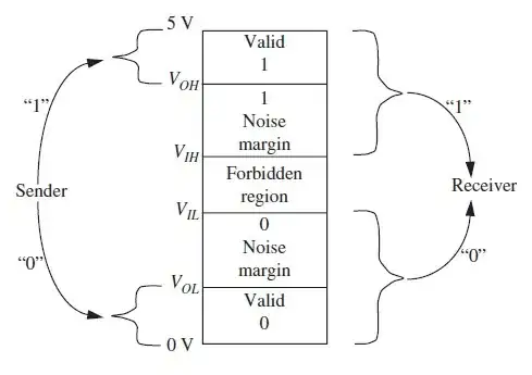
A convention could be defined:
A problem with this approach arise when the input voltage crosses the threshold. At some point in time, it is at the threshold. And if there is some noise on the signal, the pin could see a 0 or a 1 bouncing very quickly. Imagine that the input is a clock signal and you would see clock edges where you don't want to.
The following approach solves that problem:
There is are two thresholds: Namely Vih and Vil. A signal is considered as 0 if it is below Vil and a 1 if above Vih. The two threshold are separated by a grey zone that prevent toggling by added noise (up to a certain level).
The following figure found on the web explains that feature:
The resistor in you schematics is here to make sure that, when the button in not pressed, the voltage at MCLR is above Vih (not in the forbidden region).
But, as @Spehro Pefhany expains in his answer, this is not enough.
A press button is not prefect. When you release it, you may (and you will, actually) see bounces.
This picture, also found on the web shows this:

A way to overcome this issue is to "smooth" the output signal using a capacitor as shown in the datasheet of the micro controller. The capacitor would be quickly discharged through the low impedance path of the pressed button, but would take some time to charge though the resistor when the button is open due to bounces. If you choose the right resistor-capacitor pair, you could make sure that it would take longer to the MCLR voltage to cross the Vil that it take to the button to stop bouncing.
This resistor is known as pull up resistor. It is connected to the first pin of PIC for resetting. When this pin is grounded or active low PIC get reset. So for making IC in working mode, this pin is pulled up through this resistor.A switch is used to ground the pin to reset the program.
From the PIC16F877 datasheet:
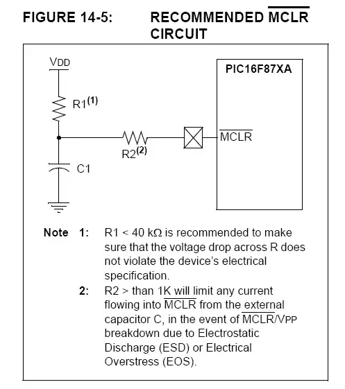
In this case, the switch takes the place of the capacitor, to cause a reset whenever the switch is pressed (as opposed to only when the power is applied and the capacitor voltage is presumed to be about zero).
The upper limit to the value is the recommended 40K ohms (relatively high values will increase noise sensitivity as well). The lower limit is set by how much current you want to draw out of the power supply when the switch is pressed. A few K to 15 or 20K is a reasonable range for most purposes.
Note that when there is a capacitor, there should also be a series resistor, according to Microchip, of something like 1K or 2K. It's not a bad idea to put it in there even with no capacitor (only a switch) because of possible ESD transmitted through the switch actuator.
There are several answers explaining how a pullup resistor works, so I won't go into that. Instead I'll try to explain why it is there.
Pullup resistors are used when an input on a microcontroller needs to be controlled by several sources. For example, in your case, SW1 can be pressed to reset the microcontroller by bringing its !MCLR/VPP line low. What you don't show in your schematic is the programming interface from your programmer (e.g. ICD 3) which also needs to reset the microcontroller by bringing its !MCLR/VPP line low.
If MCLR was active high instead of low, then it would be possible for two inputs to be driving it at the same time, with slightly different voltages (for example, VCC from the switch and VPP from the programmer interface), and you could end up with all sorts of problems (especially if one input was at VCC and another at ground, creating a direct short.
Instead the devices driving the !MCLR line are configured as open-drain (or in the case of the switch, having it be an open-circuit until it is closed). Open-drain outputs can be driven low, but cannot be driven high (the default high state is tri-stated, meaning it doesn't drive the line to VCC -- instead it looks like an input). So any number of devices can be connected to an active-low line like this, and if more than one are driven low (ground), there are no problems .
However since none of these inputs are configured to drive the input high, the pull-up resistor provides the default high level (VCC), and it brought down to ground when any of the inputs go to ground.
Diagram is rather small; but that's a "pullup". It brings ~MCLR up to logic 1, except when the button is pressed. Replacing it with a wire would short out the circuit when the button was pressed.
The resistor is there to limit the current going into that pin... when the switch is open. You can reduce the resistance depending on current requirement for the ic.
When the switch is closed, the resistor is there to prevent Vcc from shorting to ground.