I had intended to only comment, but I found I had too much to say:
Follow Spehro and Alexey's advice. There are multiple issues here. Perform all of the fixes, even if you find that just a snubber or decoupling capacitor seems to do the trick.
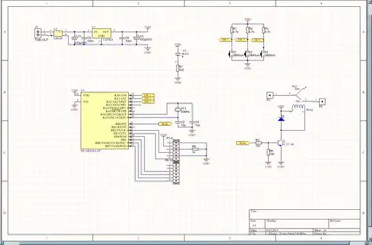
The load is 220AC. Trying to control bell.
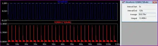
Please note that when there is no load, the relay command fully works, without resetting the microcontroller.
This would seem to indicate that switching the bell is the source of a spike causing the reset. Do not omit the snubber &/or MOV that Spehro suggests since the relay is switching an inductive load. I have seen too many problems with switched inductive loads causing resets in industrial equipment to consider the need for a snubber and/or MOV to be merely a "band-aid". Besides the reset issue, without suppression of the spike, additional arcing will occur on the relay contacts shortening the life of the relay. You can buy a snubber or make your own.
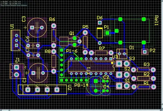
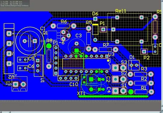
The added decoupling capacitor (suggested by Alexey) needs to have the shortest path possible to the PIC power/gnd pins. The cut-up ground plane does not accomplish this.
The placement of the power/gnd pins on the PIC is a little difficult to accomplish a short path to the decoupling capacitor without either running traces between pads (could require longer-skinnier pads), or placing the decoupling capacitor on the back side.
You could "kludge" the decoupling capacitor to the existing board by cutting the leads short and either soldering it directly to the PIC power/gnd pins on top of the PIC, or soldering it to the pads on the solder-side of the board.
A few more unrelated comments regarding the board layout. Since P1 and P2 are on 220VAC, isolate them to one area of the board with no other traces (even the gnd plane) even close. See Creepage distance for PCBs handling line voltage AC? ... I would also not put the switches too near the AC since fingers will be in there. Also consider adding some mounting holes to the board.