4

I'm trying to build my own Bench Power Supply but I'm having a hard time to find a good design (circuit/project) for it.

Here are my requirements:

  • Input: main using a 18V 2A transformer
  • Output: 0-18V
  • Current: 0-1.5A
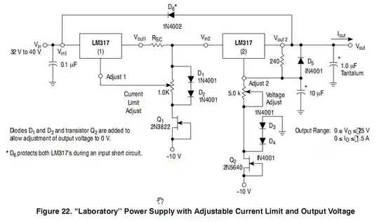
  • Current Limiting controlled by a potentiometer
  • Voltage output controlled by a potentiometer
  • And I'd love it to be based on the LM317

I know there are some designs with two LM317, one limiting current and the other controlling the voltage output, but I couldn't find any good reference for those circuits.

Chetan Bhargava
  • 4,612
  • 5
  • 27
  • 40
mlemos
  • 65
  • 1
  • 2
  • 9
  • 2
    LM317 is a bad choice. 18VAC in the secondary is ~25.4V RMS, if you regulate down to 1V at 1.5A that's 36.7W of dissipation which the device won't be able to handle without a few cubic meters (ish) of heatsink. – Adam Lawrence Feb 23 '14 at 01:06
  • LM317 won't go below 1.2V either... – Matt Young Feb 23 '14 at 06:38
  • You'd have to chain multiple TO220 LM317 and give a heatsink to each. Not a good idea. – Lundin Aug 17 '18 at 07:51

3 Answers3

6

There is a schematic in the ON-Semi datasheet

enter image description here

It needs a negative voltage that feeds the two depletion mode JFETs, they operate as constant current sources and in conjunction with the two diodes connected to the output provide about -1.4V to the pot.

alexan_e
  • 11,070
  • 1
  • 28
  • 62
  • Thanks @alexan_e . I saw that design on the datasheet, but I wasn't sure about a few things: a) I was not able to find the Q1 and Q2 components. Can you suggest me any alternatives to them? They seem to be obsolete. b) Do I need to provide exactly -10 for Q1 & Q2? Can it be something around -10? How well needs this -10 be in terms of stabilization? c) What is the value for Rsc? – mlemos Feb 23 '14 at 13:48
  • @mlemos The -10 voltage doesn't have to be exact , it can even be -8 or -12 or lower. The Jfet work as constant current source so the current will change slightly (IDSS parameter) but this is not a problem. For calculation of the resistor you can refer to figure 23 page 9 of the datasheet. You can also refer to a similar post http://electronics.stackexchange.com/q/41549/33841 , it suggests an alternative Jfet. – alexan_e Feb 23 '14 at 14:15
  • The voltage rating of the 2N3822 JFET is only 50V, so -10 is about as low as you would want to go with 40V in. One of them sees Vin + 10V -2V (or so). – Spehro Pefhany Feb 23 '14 at 15:51
  • @SpehroPefhany His input is not 40v but about 25v from a 18v transformer. – alexan_e Feb 23 '14 at 16:07
  • 1
    Sure. Should be okay for him even with bad transformer regulation etc. Just in case someone else tries to use the circuit as drawn I thought I'd mention it. – Spehro Pefhany Feb 23 '14 at 16:12
  • Thansk @alexan_e . Is it correct to assume that Vref they reffer to in the datasheet is the 1.25V of the LM317 and the Idds is a characteristic of the transistor? – mlemos Feb 24 '14 at 11:57
  • Thanks @SpehroPefhany . Since I'm using a 18+18V 2S transformer, can you suggest me a way to hookup the transformer to the the regulator circuit? I wondering if I can take the 0V & -18V to generate the necessary negative tension to feed the transistors and the 0V & +18V to feed the rest of the circuit. – mlemos Feb 24 '14 at 11:58
  • The obvious way is to use two diodes for your +V and two more for your -V with the CT grounded (a bridge rectifier can be used for all four diodes). You lose some current capability of your transformer that way. There are other approaches, but a bit too complex to describe here. – Spehro Pefhany Feb 24 '14 at 13:10
  • @mlemos Vref is LM317 Vref, about 1.25v. IDSS is a jfet characteristic (drain-source saturation current). IDSS will be fairly low compared to the output current so it can be omitted from the calculation formula (it's about (2-10mA) for 2N3822). – alexan_e Feb 24 '14 at 14:12
  • Thanks @alexan_e . I decided to go for a simpler design. I tried to have a easier circuit and I quit on having the voltage from 0 to 15 and I accepted to go from 1.25V to 15V. Now my circuit is like this: ![Bench Power Supply Design #2](http://blog.fazedores.com/wp-content/uploads/2014/03/bench-powersupply-design2.png). Do you have any comments on this design? I'm worried about the current regulation circuit, their resistors and potentiometer power specs and the transformer. But I believe it is going to work, right? – mlemos Mar 05 '14 at 13:34
  • @mlemos Potentiometer P1 is in series with the output which means that the power consumption can be up to 23w (for 1.5A), where will you find such a power potentiometer? – alexan_e Mar 05 '14 at 13:53
  • @alexan_e but for the maximum current (1.5A) the pot has to be on its minimum value (~0), so we'll have power close to zero, right? However the R1 will be at 1.2W. Or am I getting lost here? – mlemos Mar 05 '14 at 14:11
  • @mlemos the 23W I mentioned were a brainfart so please ignore. The max power consumption on the pot will be when the resistance is equal to R1 (0.8 Ohm). With that resistance (0.8+0.8 = 1.6 Ohm) the current will be 1.25v/1.6R = 0.781A. The power consumption on the pot will be P=0.781*0.781*0.8 = 0.488W so basically the max consumption on the pot will be 0.5W. – alexan_e Mar 05 '14 at 22:06
  • @alexan_e thanks! Now the big question, do you believe I can find such a 10 ohms potentiometer? If not, what do you suggest me to do? – mlemos Mar 06 '14 at 00:50
  • @mlemos I forgot to mention that the highest consumption on R1 will be when The pot is set to 0, in that vase the current will be 1.25v/0.8R=1.56A and power on R1 P=1.56*1.56*0.8=1.95W. I'm not sure about the pot specs, I've never used them in places where I cared about the power rating, but a search in google showed that there are 0.5w pots available. – alexan_e Mar 06 '14 at 07:35
  • @alexan_e thanks again. I'll try to build some prototypes over the weekend and I'll let you know the results. I'll also test another design for the current regulation as this one ![LM317 Current Regulation](https://www.dropbox.com/s/7kj90gqx7hvht64/Screenshot%202014-03-05%2022.41.28.png). I was not able to find that specific JFET or any equivalent but I'll try something close to that. – mlemos Mar 06 '14 at 17:02
2

You can use the circuit alexan_e presented and replace the obsolete JFETs with current regulator diodes. Compared to the loose tolerance 2N3822 (\$2mA \lt I_{DSS} \lt 10mA\$), they are much more tightly specified.

Power dissipation rating is a little close on the NSI50010YT1G, though, so give it lots of copper and don't allow ambient temperature \$T_A\$ to get too high.

Or you could use the IXYS TO-220 450V IXCP10M45S, which should be bulletproof (but more expensive).

Spehro Pefhany
  • 376,485
  • 21
  • 320
  • 842
  • Thanks @SpehroPefhany . How should I connect this component to the circuit? – mlemos Mar 07 '14 at 18:05
  • @mlemos They're connected just the same as the JFET in your schematic. Gate connected to source. – Spehro Pefhany Mar 07 '14 at 19:04
  • and with the same negative sourcing, right? Does this negative sourcing can be really well regulated and filtered or I can solve it with just a bunch of diodes and caps straight from the 'negative' output of a transformer? – mlemos Mar 07 '14 at 19:12
  • Yes, you could use a 50/60Hz charge pump provided the caps are big enough. – Spehro Pefhany Mar 07 '14 at 19:21
0

You should use switching regulators. TI has some grate products to help, including modules (cost more but are simpler. just add a pot and filter for instant power supply. we used one to power a robot through an umbilical and found the accuracy was very good [much better than we needed]) but regardless switching regulator will allow high current with low power dissipation. also many of the parts out there have a signal line separate from power output allowing the regulator to even compensate for any voltage drops (from ammeter for instance) making the Output what you want.

Wolf-Kun
  • 101
  • 1
  • OP requested LM317. Namely. Linear regulators has some disadvantages but also some advantages over switching regulators. OP probably has some reason for LM317. – Chupacabras Apr 29 '17 at 21:55
  • @Chupacabras You can still use a switch reg as first regulator, then put a LDO after it. That way you get the advantage of the LDO (less noise) without massive heat. – Lundin Aug 17 '18 at 08:04