The understanding of specific circuit solutions is based on revealing the basic ideas behind them. So let's see what these ideas are in the case...
To produce current, according to Ohm's law I = V/R, we need only voltage and resistance. So, if the load was pure resistive, we would need only a voltage source to produce current. By changing the voltage, we can set the desired current magnitude.
But if the load behaves as a voltage source (e.g., a rechargable battery, capacitor, Zener diode, short connection, negative resistor, etc.), we need additional resistance in series to set (limit) the current. Thus, in general case, the current source is made by two elements in series - a voltage source with voltage V and resistor with resistance Ri... and it is connected to a load with voltage VL and resistance RL. These four elements are connected in a circle and each of them affects the magnitude of current determined by the ratio of the total voltage Vt and resistance Rt; I = Vt/Rt = (V ± VL)/(Ri ± RL). In this arrangement, the input voltage source tries to set the current by its voltage V and resistance Ri while the load interferes with it by its voltage VL and resistance RL. Both the source and load influence the common current and the problem is to eliminate the impact of the load on the current.
The simplest way (typical for electric circuits) is to increase enormously both the voltage and resistance of the input source (this is the well-known definition of the ideal current source from textbooks on electrical engineering). They are high but constant (static)... and this is the trouble. Thus the load voltage and resistance become negligible compared to those of the input source. It is clear that making a good current source in this way is associated with big power losses in resistance.
The more clever way (typical for electronic circuits) is to make the source voltage or resistance varying. They are dynamic but low... so power losses are low... and this is the profit. We have the illusion of extremely high (differential) resistance but the actual (static) resistance is low. Let's see how this idea is put in practice...
The trick is that when the load increases/decreases its voltage or resistance, the source decreases/increases its voltage or resistance with the same value; so the current does not change.
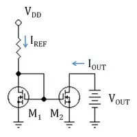
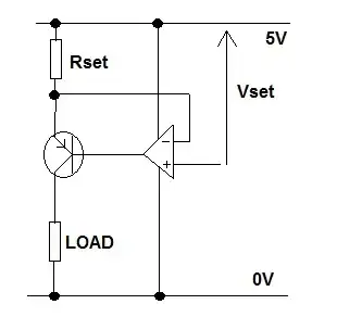
This compensation can be done without any negative feedback by using a following voltage source (the so-called "bootstrapping") or a current-stabilizing resistor (implemented by a BJT or FET with a constant input voltage).
One variation of this technique is, instead to change the very source voltage, to add additional voltage in series to the constant source voltage thus compensating for the impact of the load. This idea is realized, for example, in the op-amp inverting current source.
Another more extravagant idea is to inject additional current into the load by connecting an additional current source in parallel to the main input source. It is implemented in the Howland current source.
You can see more about these techniques in my circuit stories about constant current sources.
As a conclusion, the power of this approach is that knowing basic ideas, we can explain and realize concrete circuit configurations from the past, present and future (implemented by tubes, BJT, FET, op-amps, etc.)