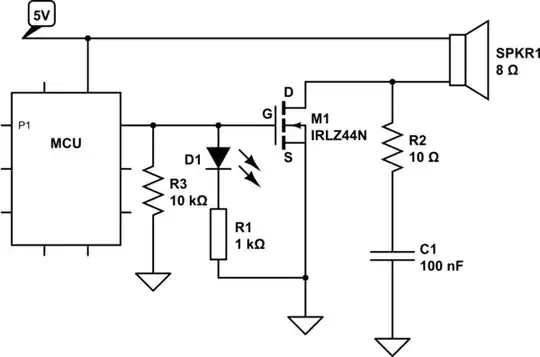
simulate this circuit – Schematic created using CircuitLab
I use D1 to visually indicate the active transistor. However, gate pin acts as if it were floating. What is wrong with my gate-grouding mechanism?
Obviously, small current originates somewhere, even with MCU's gate-facing pin = LOW. Replacing the MCU with the battery doesn't resolve the problem - weak noise comes out of the speaker. If, i.e. LED is introduced instead - if flashes slightly. If 5V RAIL is replaced with i.e. 12V, in OFF mode I can still see 10V on the output.
Removing D1 solves everything.
How can D1 cause M1 gate to float?